

Introduction
Our database of connections is always growing, but we have started here with the AISC standard connections commonly used across steel connection design projects.
How to Use Workset Files
Quick how to video of how to download and open these files in IDEA StatiCa.
Beam - Column Flange Joints
Carousel of Beam-Column Flange
Weld Rupture
The AISC Specification includes provisions for groove welds, fillet welds, and plug and slot welds. Of these, complete joint penetration (CJP) groove welds and fillet welds are the only types that can currently be defined in IDEA StatiCa.
CJP groove welds and butt welds in IDEA StatiCa, are modeled by directly connecting the components using multi-point constraints. The multi-point constraints introduce no flexibility. Also, the strength of these welds is not checked since the strength of the CJP groove welds is controlled by the base metal.
Fillet welds are also modeled using multi-point constraints and an equivalent weld shell element that approximates the elastoplastic behavior of the weld. The forces in these shell elements are extracted and used as required strengths for comparison to available strengths computed according to the AISC Specification.
The available strength of welds is defined in AISC Specification Section J2.4. For fillet welds, the nominal strength is the product of the nominal stress of the weld metal, Fnw, the effective area of the weld, Awe, and a directional strength increase factor, kds. AISC Specification Table J2.5 sets Fnw = 0.6FEXX and references AISC Specification Section J2.2a for the definition of Awe. For each weld segment, Awe is taken as the throat thickness times the length of the weld segment. The reductions to the effective length for long welds in AISC Specification Section J2.2b are not applied; however, the effects of long welds are captured explicitly as described in the entry on Deformation Compatibility in Long Connections.
The directional strength increase factor is defined in AISC Specification Section J2.4. When strain compatibility of the various weld elements is considered (as is the case in IDEA StatiCa because the stiffness of the welds and connecting elements are explicitly modeled), kds is a function of the angle between the line of action of the required force and the weld longitudinal axis. IDEA StatiCa determines the line of action from the internal forces in the equivalent weld shell element and computes kds and the nominal strength for each weld segment.
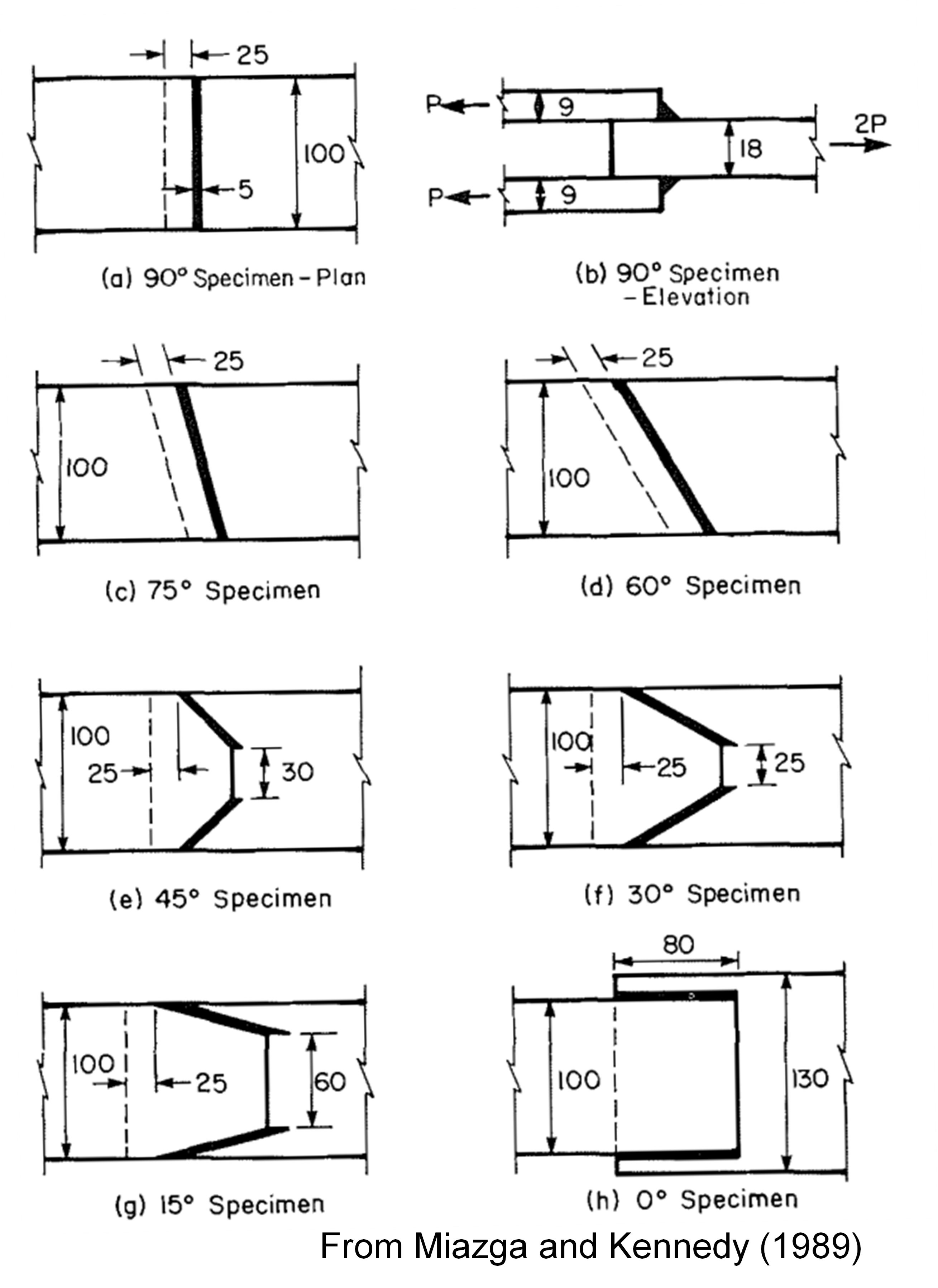
To illustrate the effect of the directional strength increase, consider the welded specimens tested experimentally by Miazga and Kennedy (1989). The specimens had loading angles of 0, 15, 30, 45, 60, 75, and 90 degrees as shown in the figure below where the units are millimeters. The plates were fabricated with CAN3-G40.21-M8 grade 300W steel. The exterior plates had a measured yield strength of 52.8 ksi. The interior plates had a measured yield strength of 50.2 ksi. E48014 electrodes with a nominal strength of FEXX = 70 ksi were used.

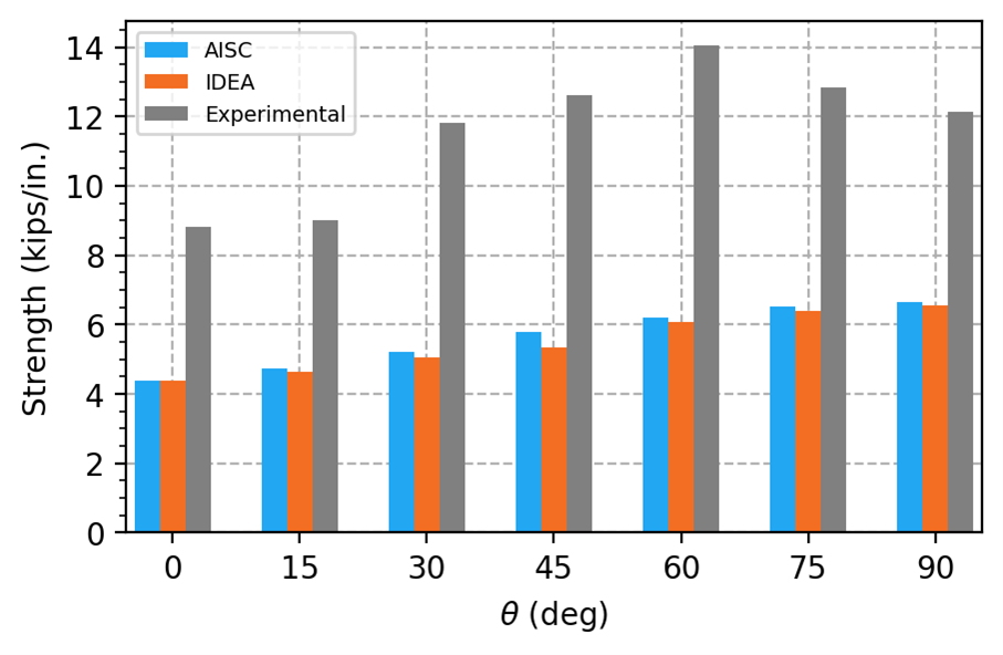
The maximum permitted applied loads were determined for each specimen in IDEA StatiCa using models with measured plate material properties, nominal filler metal properties, and including resistance factors. The maximum permitted applied loads were normalized by the total length of weld in the connection and are shown in the figure below. Also shown are the design strength according to the AISC Specification (including the directional strength increase factor and resistance factor) and the experimental strength.
The angle of loading measured from the weld longitudinal axis for each specimen, as output by IDEA StatiCa in the weld results, is listed in the table below.
| Geometric \(\theta\) (deg) | IDEA \(\theta\) (deg) |
| 0 | 14.7 |
| 15 | 21.1 |
| 30 | 34.0 |
| 45 | 49.1 |
| 60 | 58.8 |
| 75 | 72.6 |
| 90 | 89.9 |
The IDEA StatiCa and AISC Specification strengths are both much less than the experimental strengths. There are several reasons the experimental strengths are higher: they do not include resistance factors, the actual filler metal strength is likely more than the nominal strength, and the actual failure area of the weld is likely greater than assumed in design calculations.
The strengths from IDEA StatiCa are slightly less than those according to the AISC Specification, but both show an increase with loading angle. Furthermore, the geometric angle of the specimen differs from the angle of loading measured from the weld longitudinal axis as output by IDEA StatiCa. These differences occur because welds are divided into short segments when modeled in IDEA StatiCa. Unlike traditional calculations where the demands along the length of the weld are assumed to be uniform, the weld segments experience different demands based on the stiffness of the weld and connecting elements. The angle output by IDEA StatiCa is for the weld segment that has the greatest utilization ratio. Often this is a segment at the end of a weld. For these specimens, the aggregate effect of the non-uniform demands is a slight reduction in strength.
A special case applies for fillet welds to the ends of rectangular HSS loaded in tension where kds = 1.0. In IDEA StatiCa, the directional strength increase factor is not used for fillet welds to the ends of rectangular HSS, regardless of loading.
AISC Specification Section J2.4 also defines the strength of the base metal. For fillet welds, AISC Specification Table J2.5 references AISC Specification Section J4 for base metal checks. Base metal strength checks are described in greater detail in the entry on Weld Base Metal Strength.
Weld Base Metal Strength
In welded connections, the strength of the connecting elements adjacent to the weld is called base metal strength. In many cases, potential limit states can be identified, and the available strength of the base metal can be computed using the provisions of AISC Specification Section J4. The evaluation of these limit states in IDEA StatiCa is described in entries on the individual limit states, including Tensile Yielding, Tensile Rupture, Shear Yielding and Rupture, and Block Shear Rupture.
However, in some connections, potential limit states adjacent to the weld are hard to identify, and the available strength of the base metal cannot be directly computed by hand. For these cases, the AISC Manual provides Equations 9-6 and 9-7 for the minimum base metal thickness that matches the weld with some assumptions. This equation is not evaluated in IDEA StatiCa since potential base metal limit states need not be identified a prior, and strength is assessed with the 5% plastic strain limit. However, engineers may still use the limit to size welds and connecting elements.
IDEA StatiCa provides an option to check base metal capacity at the fusion face. This check can be enabled in the “Code setup” window. This check is not commonly performed in US practice and is generally not necessary when the filler metal is appropriately matched to the base metal. The commentary on AISC Specification Section J2.4 states that tests have demonstrated that the stress on the fusion area is not critical in determining the shear strength of fillet welds.
Bolt Shear and Tensile Rupture
The available strength of bolts subject to tension or shear is defined in AISC Specification Section J3.7. The available strength of bolts subject to combined tension and shear is defined in AISC Specification Section J3.8. IDEA StatiCa uses these provisions directly to compute available strengths, compared to required strengths determined from nonlinear analysis. As specified, the required tensile strength determined from nonlinear analysis includes tension resulting from prying action.
A footnote in AISC Specification Table J3.2 requires that the nominal shear stress, Fnv, of A307 bolts be reduced when the grip of a bolt is greater than five times its diameter. This reduction is not implemented in IDEA StatiCa. Therefore, the nominal shear stress of long A307 bolts needs to be manually adjusted in the materials tab.
Bearing and Tearout at Bolt Holes
The strength of bolts in shear can be limited by bearing or tearout at the bolt holes. It is sometimes common practice to evaluate bearing and tearout separate from bolt shear rupture. However, bolt groups can fail with some bolts rupturing and others tearing out. A user note in AISC Specification Section J3.7 states “The effective strength of an individual fastener may be taken as the lesser of the fastener shear strength per Section J3.7 or the bearing or tearout strength at the bolt hole per Section J3.11. The strength of the bolt group is taken as the sum of the effective strengths of the individual fasteners.”
IDEA StatiCa evaluates the strength of each bolt individually, with required strengths determined from the nonlinear analysis and available strengths calculated using the provisions of the AISC Specification. This evaluation complies with the user note in AISC Specification Section J3.7. However, IDEA StatiCa does not simply sum up the effective strengths of the individual fasteners. The approach taken by IDEA StatiCa can result in a conservative underestimation of strength.
Consider the three-bolt connection shown below. The connection is short and the stiffness of the three bolts is equal because the load-deformation response for bolts in IDEA StatiCa does not depend on edge distance, therefore the applied load is shared approximately equally among the bolts. The strength of the bolt with the 1 in. edge distance is controlled by tearout. IDEA StatiCa indicates failure when the first bolt reaches 100% utilization. Since the bolt with 1 in. edge distance has the lowest available strength (ϕrn = ϕ1.2dtFu = 17.4 kips), it reaches 100% utilization first. The other bolts are stronger (ϕrn = 35.8 kips, AISC Manual Table 7-1) but they do not reach 100% utilization, resulting in a connection strength of 52.5 kips. By traditional calculations, each bolt is assumed to reach its effective strength, resulting in a connection strength of 89.0 kips, 70% greater than the strength from IDEA StatiCa.
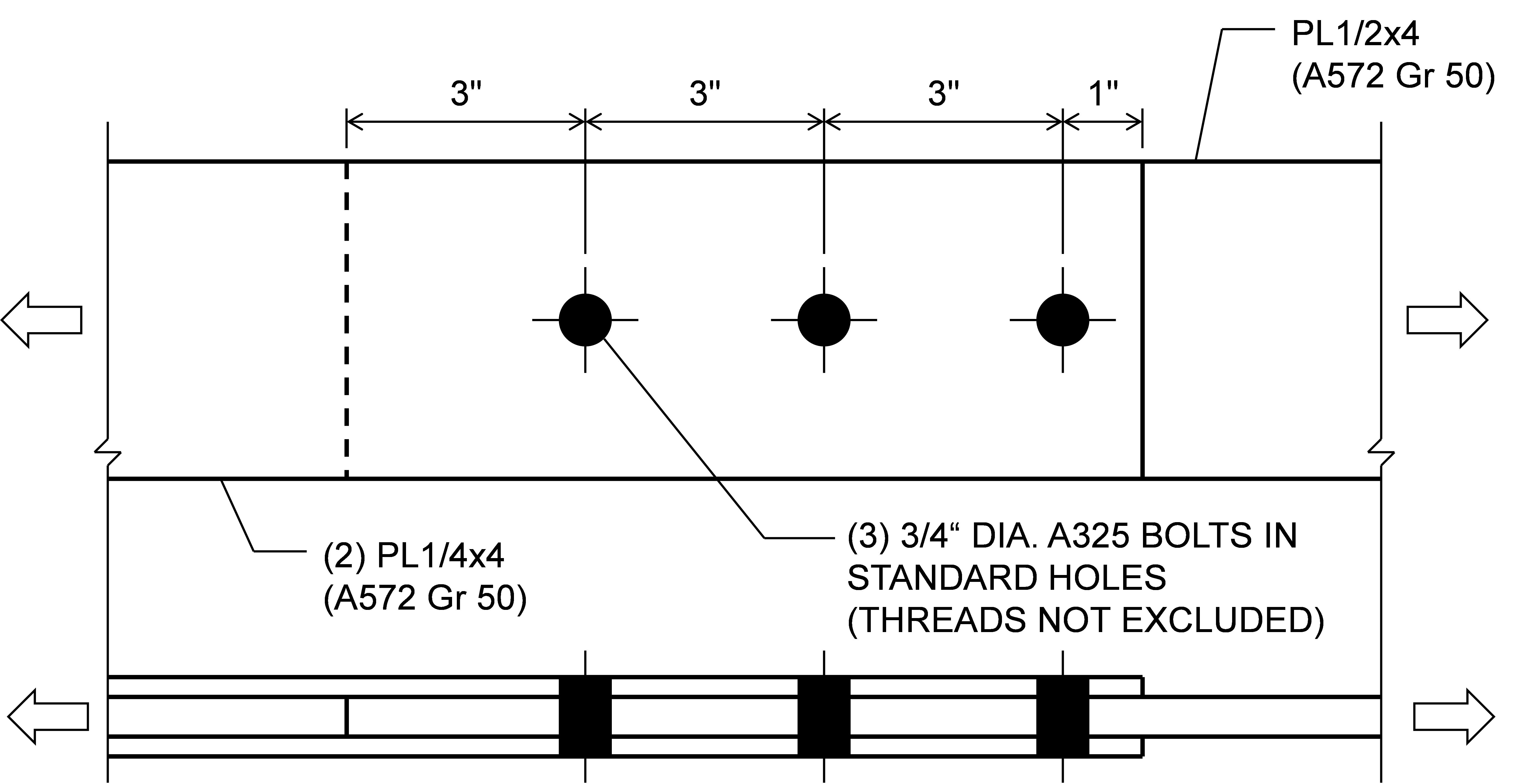
Three-bolt bolted connection
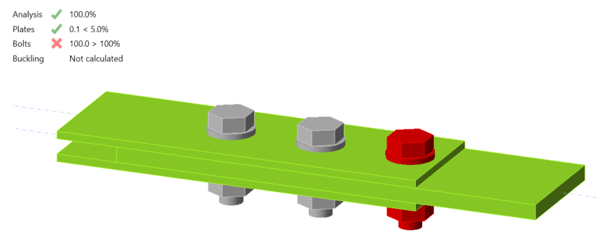
Three-bolt bolted connection with 57.5 kips of applied load
Two sets of equations are provided in AISC Specification Section J3.11a, one when deformation at the bolt hole at service load is a design consideration and one when deformation at the bolt hole at service load is not a design consideration. The choice of whether deformation at the bolt hole at service load is a design consideration can be made in the “Code setup” window.
Different equations are also provided in AISC Specification Section J3.11a for long-slotted holes when the slot is perpendicular to the direction of force. Slotted holes can be defined in IDEA StatiCa using the plate editor. The bearing and tearout equations in the AISC Specification for long-slotted holes are used for all slotted holes in IDEA StatiCa, regardless of slot length.
AISC Specification Section J3.11b requires the use of the bearing provisions of Section J7 for bolts or rods that pass completely through an unstiffened box member or hollow structural section (HSS). This provision is not implemented in IDEA StatiCa and bearing is evaluated in such connections as though they are regular bolted connections with all plies making firm contact. A warning is provided in the report if the bolt grip length is larger than the sum of the thicknesses of connected plates.
When evaluating tearout, IDEA StatiCa determines the clear distance, in the direction of the force, between the edge of the hole and the edge of the adjacent hole or edge of the material, lc, using the direction of force for each bolt from the nonlinear analysis. This feature is particularly helpful for eccentrically loaded bolt groups where the direction of force varies from bolt to bolt. The tearout limit state was investigated for bracket plate connections in this article and for single plate shear connections in this article.
Bearing (Local Compressive Yielding)
AISC Specification Section J7 defines the available strength for the limit state of bearing (local compressive yielding). These provisions apply to specific cases of contact between steel components but are not implemented in IDEA StatiCa.
For finished surfaces and ends of fitted bearing stiffeners, while the contact bearing pressure is not checked against the limit prescribed in the AISC Specification, stresses in contacts can be plotted and yielding of the steel components often provides a more controlling limit since the allowable bearing pressure exceeds the yield strength.
IDEA StatiCa evaluates the bearing strength of bolts or rods that pass completely through an unstiffened box or HSS member as though they are regular bolted connections with all plies making firm contact and not using the provisions of AISC Specification Section J7. A warning is provided in the report if the bolt grip length is larger than the sum of the thicknesses of connected plates. See also Bearing and Tearout at Bolt Holes.
Expansion rollers and rockers cannot be modeled in IDEA StatiCa. Pins were introduced to IDEA StatiCa in version 24.0 and are currently only available for design by Eurocode.
Slip
Connections are required to be designed as slip-critical when they are subject to fatigue load with reversal of loading direction, when they use oversized holes, when slip at the faying surfaces would be detrimental to the performance of the structure, and for other reasons. Available strength for the limit state of slip is defined in AISC Specification Section J3.9 with additional provisions in Section J3.10 for combined tension and shear in slip-critical connections. IDEA StatiCa uses these provisions directly to compute available strengths which are compared to required strengths determined from nonlinear analysis.
The slip coefficient, μ, is defined in the code setup. The factor for fillers, hf, is determined automatically.
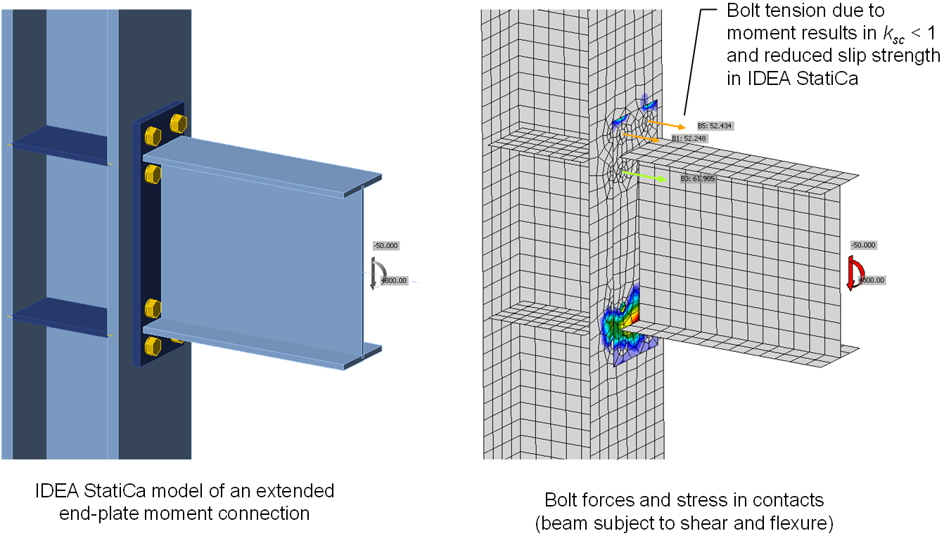
Differences between IDEA StatiCa and hand calculations can occur because of the reduction factor for tension, ksc, defined in AISC Specification Section J3.10. IDEA StatiCa uses the tension in the bolt from the nonlinear analysis to calculate ksc, even if the tension in the bolt was not caused by applied tension that reduces the net clamping force. For example, in an extended end-plate moment connection with a slip-critical connection between the end plate and the column flange (such as shown below), moment in the beam causes tension in the bolts in IDEA StatiCa. Physically, any loss of clamping force near the bolts on the tension side of the beam due to moment will be offset by an increase in clamping force near the bolts on the compression side of the beam. In hand calculations, the factor ksc would not be used for this connection (unless the beam has a net tension force). But since IDEA StatiCa evaluates bolts individually, ksc is conservatively applied to the bolts on the tension side of the beam reducing the overall slip strength of the connection. Incidental tension in a predominantly shear-loaded connection and tension from prying action are also conservatively included when calculating ksc in IDEA StatiCa.
AISC Specification Section J3.9 requires that slip-critical connections be designed for the limit states of bearing-type connections in addition to slip. IDEA StatiCa does not check bolt rupture, bearing, or tearout for bolts designated to transfer force through friction. Additionally, slip-critical connections are modeled differently than bearing-type connections in IDEA StatiCa. In slip-critical connections, the forces are transferred from one plate to another over a larger area more representative of force transfer through friction. The larger spread of transfer forces can lead to increased strength of connecting elements for limit states such as block shear rupture. For most connections, slip strength is less than the strength for the limit states of bearing-type connections. However, engineers should be aware of these limitations and address them in design. It is recommended that slip-critical connections be analyzed twice in IDEA StatiCa: once as a slip-critical connection (i.e., with shear force transfer type set to “Friction”) and again as a bearing type connection (i.e., with shear force transfer type set to “Bearing – tension/shear interaction”) to ensure all limit states are evaluated appropriately.
Tensile Yielding
Tensile yielding is among the most fundamental limit states in structural steel design. The nominal strength for tensile yield is defined in AISC Specification (2022) Section D2 for tension members and Section J4.1 for connecting elements as the specified minimum yield stress, Fy, times the gross area, Ag. Despite the simplicity of this equation, it is not used to assess strength in IDEA StatiCa. Members and connecting elements are modeled in IDEA StatiCa with shell elements that are assigned a nonlinear stress-strain relationship consisting of a linear elastic region and a linear plastic region. Shell elements can experience stress along multiple axes and the stress-strain relationships account for this. If subject to uniaxial stress, the stiffness in the elastic range is the modulus of elasticity, E, the stiffness in the plastic range is one-thousandth of the modulus of elasticity, E/1000, and the transition between elastic and plastic occurs at a stress of Fy times a resistance factor of 0.9 for LRFD or divided by a safety factor of 1.67 for ASD.
Instead of limiting the required strength to be no more than the available strength (e.g., Ru ≤ ϕRn), IDEA StatiCa limits plastic strain to 5%. While this is a fundamentally different assessment, resulting strengths for tensile yield of the gross section of a member or component from the two approaches will never differ by a large amount. Minor differences can arise for two reasons: 1) the small increase in stress after yielding in IDEA StatiCa and 2) small differences in cross-sectional area.
A small post-yield stiffness (one-thousandth of the elastic stiffness) is used in IDEA StatiCa to avoid the computational difficulties that would arise with zero post-yield stiffness. At the 5% plastic strain limit, this results in approximately 0.05×E/1000 = 0.05×(29,000 ksi)/1000 = 1.45 ksi stress above the yielding stress. For ASTM A992 steel with a Fy of 50 ksi and using LRFD, tensile yield initiates in IDEA StatiCa at 0.9×50 ksi = 45 ksi. The extra 1.45 ksi of stress accumulated post-yield can lead to an approximately 3% increase in strength.
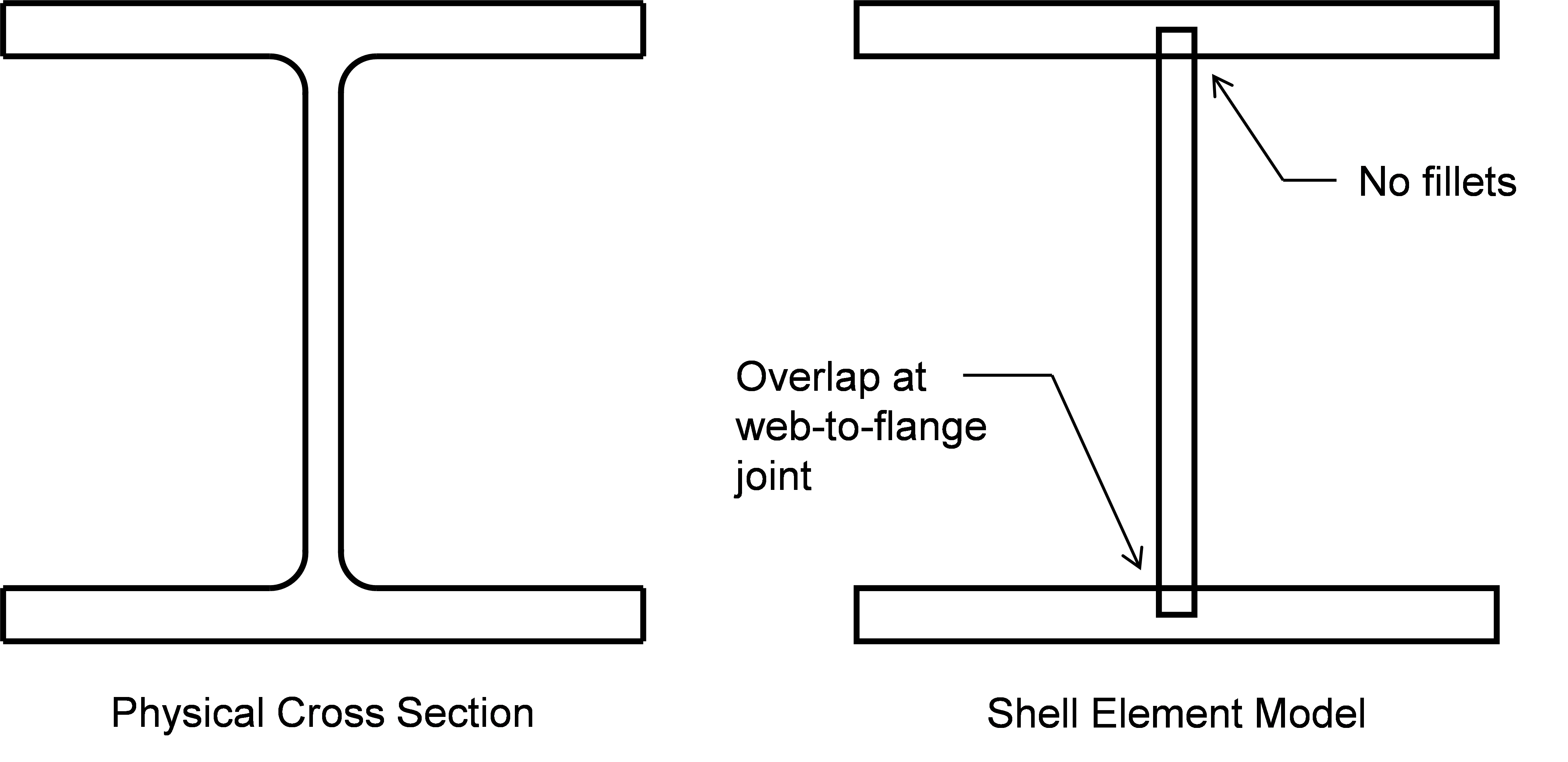
Structural steel members are modeled with shell elements in IDEA StatiCa resulting in some simplifications of the physical geometry. The shell elements only represent rectangular components thus fillets are neglected. Additionally, since shell elements are connected at nodes located at the center of thickness, there is some overlap at joints of cross-sectional elements. The figure below shows the simplifications for a wide flange shape. The simplifications cause small differences in cross-sectional area which can affect tensile yield strength. For a W14x159, the cross-sectional area listed in AISC Manual Table 1-1 is 46.7 in.2. The cross-sectional area when modeled as in IDEA StatiCa is 2bftf+(d-tf)tw = 2(15.6 in.)(1.19 in) + (15.0 in. – 1.19 in.)(0.745 in.) = 47.4 in.2, where the cross-sectional dimensions were also determined from AISC Manual Table 1-1. This is a 1.5% difference.
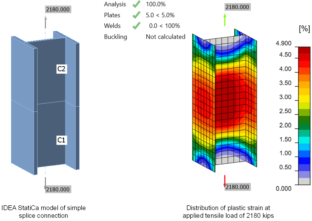
The overall effect of these minor differences can be observed in a simple IDEA StatiCa model of a splice connection between two W14x159 (ASTM A992) steel shapes. The splice is butt welded (e.g., CJP) and loaded in tension. Per the AISC Specification (2022), the design strength of the wide flange tension member is 0.9×(50 ksi)×(46.7 in.2) = 2,100 kips. The maximum load that can be applied to the connection in IDEA StatiCa (version 22.1) is 2,180 kips, 4% greater than the design strength as calculated per the AISC Specification. The distribution of plastic strain in the connection shows that the full cross-section has yielded.
Tensile Rupture
Provisions for the limit state of tensile rupture are in AISC Specification Chapter D. These provisions are referenced in AISC Specification Section J4.1 for connecting elements. The nominal strength for tensile rupture is calculated as the tensile strength of the material, Fu, times the effective net area, Ae. The effective net area accounts for material removed, including bolt holes, and the effect of shear lag through the shear lag factor, U, defined in AISC Specification Table D3.1. A resistance factor of ϕ = 0.75 is applied to the nominal strength to determine the design strength.
The limit state of tensile rupture is not directly evaluated in IDEA StatiCa. It is captured by limiting the amount of plastic strain any component can experience. The default plastic strain limit in IDEA StatiCa is 5%. Neither Fu nor the resistance factor of ϕ = 0.75 are used in IDEA StatiCa. IDEA StatiCa uses a bilinear stress-strain relationship in which yield occurs at the yield stress of the steel, Fy, times a reduction factor equal to 0.9 by default (the user can adjust this factor). After yield, the stiffness of steel is only one thousandth of the modulus of elasticity. This post yield stiffness is included for numerical stability and does not provide any significant strain hardening. Additionally, IDEA StatiCa does not use the shear lag factors of AISC Specification Table D3.1. Instead, shear lag is modeled explicitly.
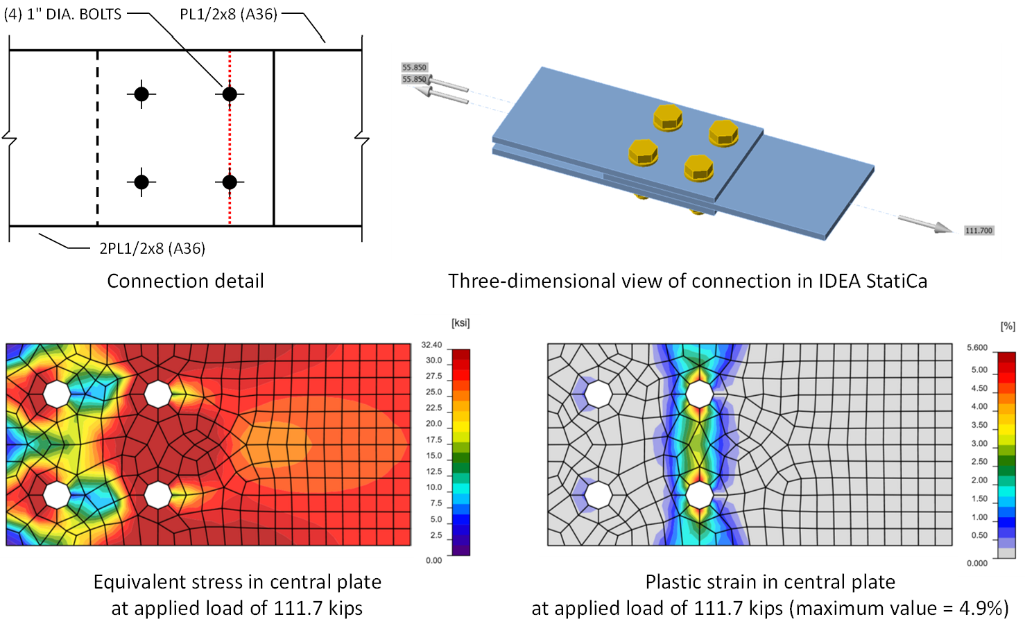
Also, the stresses that develop in connection regions are rarely purely uniaxial. IDEA StatiCa uses the von Mises yield criterion to identify when yielding occurs under these complex stress states which can lead to an apparent increase in strength. To illustrate this effect, consider the simple splice connection shown in the figure below. The strength of the central plate near the bolts controls the strength of this connection. Based on hand calculation procedures, one may expect that the strength that IDEA StatiCa will determine would be the stress at which yielding occurs times the net area (shown by a red dotted line in the figure). For this connection, the net area is (1/2 in.)×(8 in. – 2dh) = 2.875 in.2, where the diameter of the hole, dh, equals 1-1/8 in. (note that IDEA StatiCa does not include the 1/16 in. for damage described in AISC Specification Section B4.3b, see the entry on Net Area Determination for additional information - ADD ANCHOR). For LRFD, the stress at which yielding occurs in IDEA StatiCa is 0.9Fy and there is minimal strain hardening (see the entry on Tensile Yielding for additional information). For the A36 material used in this example, yielding will occur at 0.9(36 ksi) = 32.4 ksi. Therefore, one may expect that the strength of this connection in IDEA StatiCa would be (2.875 in.2)×(32.4 ksi) = 93.1 kips. However, because the stress is not purely uniaxial at the net section, the other components of stress effectively increase the yield stress normal to the net area, and 5% plastic strain is not achieved until an applied load of 111.7 kips.
Taken individually, the differences between traditional calculations and IDEA StatiCa result in lower strengths in IDEA StatiCa (only using Fy and not Fu), higher strengths in IDEA StatiCa (using a material strength reduction factor of 0.9 instead of ϕ = 0.75), and different strengths depending on the specific connection (explicitly modeling shear lag instead of using the shear lag factor, U). Taken together, the differences usually, but not always, result in equal or lower strength from IDEA StatiCa than from traditional calculations.
The limit state of tensile rupture was investigated in this study through comparison to hundreds of experimental results. The results show that IDEA StatiCa is generally conservative, especially at the nominal strength level, but there are some cases where the available strength from IDEA StatiCa is greater than that calculated according to the AISC Specification. Using measured material and geometric properties without resistance factors applied, the strength from IDEA StatiCa was less than or equal to the experimentally observed strength for all but 12 specimens out of 529 (9 of which were fabricated with high-strength steel, Fy = 122.8 ksi) and less than or equal to the expected tensile rupture strength computed using design equations for all but 30 specimens out of 529. Using nominal material and geometric properties with resistance factors applied, the strength from IDEA StatiCa was found to be greater than the strength computed according to the AISC Specification for some connections without physical counterparts, especially plate tension members with relatively short welds, and rectangular HSS tension members. Given that the experimental data for these cases is limited, work is ongoing to determine if the differences are the result of unconservatism in IDEA StatiCa or conservatism in the AISC Specification equations.
Compressive Yielding and Buckling
The available strength of affected elements of members and connecting elements in compression is defined in AISC Specification Section J4.4. When the slenderness ratio, Lc/r, is less than or equal to 25 compressive yielding applies and the nominal strength is computed as the product of the specified minimum yield stress and the gross area (i.e., Pn = FyAg). Like for Tensile Yielding, the limit state of compressive yielding is evaluated in IDEA StatiCa with the 5% plastic strain limit.
When the slenderness ratio, Lc/r, is greater than 25, the provisions of AISC Specification Chapter E apply. Limit states in AISC Specification Chapter E include flexural buckling, torsional buckling, and flexural-torsional buckling. The nonlinear analysis performed in IDEA StatiCa is nonlinear because it includes effects such as yielding and contact. The analysis typically does not consider geometric nonlinearities such as P-Δ effects (geometric nonlinearities are considered when HSS are used as bearing members).
Engineers must also perform a linear buckling analysis to detect buckling. A linear buckling analysis can determine the elastic buckling load, expressed as a ratio of the applied load. While providing useful information that can guide design, the linear buckling analysis does not consider potential yielding that can reduce stiffness and the buckling load (i.e., inelastic buckling), nor does it consider the effects of initial geometric imperfections. Because of these limitations, to use IDEA StatiCa, the connection needs to be stocky enough that neither elastic buckling nor inelastic buckling will occur. The elastic buckling load ratio provides a convenient measure of stockiness (or slenderness).
Consider the slenderness ratio limit in AISC Specification Section J4.4 of Lc/r ≤ 25 to assume compressive yielding. A slenderness ratio of Lc/r = 25 corresponds to an elastic critical stress Fe = π2E/(Lc/r)2 = π2(29,000 ksi)/(25)2 = 458 ksi. For A36 steel, this corresponds to 14 times the factored yield stress for LRFD and 21 times the factored yield stress for ASD. For grade 50 steel, the elastic critical stress corresponds to 10 times the factored yield stress for LRFD and 15 times the factored yield stress for ASD. Accordingly, the elastic buckling load ratio should be kept greater than these ratios to avoid cases where inelastic buckling could control.
The appropriate limit on the elastic buckling load ratio varies based on the connection configuration. For plate buckling, the limit is much lower. Based on the limiting width-to-thickness limits in AISC Specification Table B4.1a, the elastic critical buckling load ratio should be kept to no less than 3 for LRFD and 4.5 for ASD . An evaluation of bracket plates identified elastic critical buckling load ratio limits of 4 for LRFD and 6 for ASD. The use of a critical buckling load ratio limit of 3 has been evaluated for bearing stiffeners (report coming soon), coped beams, and beam-over-column connections.
Elements of connections that are slender enough for inelastic buckling to occur still have strength, potentially enough strength for a given application. However, without the capability to accurately quantify inelastic buckling strength in IDEA StatiCa these cases must be avoided.
Shear Yielding and Rupture
The available strength of affected elements of members and connecting elements in shear is defined in AISC Specification Section J4.2. This section describes two limit states: shear yielding and shear rupture. For both limit states, IDEA StatiCa does not compute the available strength per the AISC Specification, but rather relies on the 5% plastic strain limit to evaluate if the connection is sufficiently strong.
In tension, the stress-strain relationship used in IDEA StatiCa is linear up to yield, with a stiffness equal to the modulus of elasticity, then linear thereafter, with a stiffness equal to one-thousandth of the modulus of elasticity. Yield in tension occurs at the specified minimum yield stress of the steel, Fy, times 0.9 for LRFD or divided by 1.67 for ASD. IDEA StatiCa uses the von Mises yield criterion to determine when yielding begins under multi-axial states of stress. According to the von Mises yield criterion, material subject to pure shear will yield when the shear stress equals the yield stress divided by the square root of 3. The inverse of the square root of 3 is approximately equal to 0.577 which is approximately equal to the 0.6 factor applied to the shear strength equations in the AISC Specification. This difference, or similar differences when the element is not strictly in pure shear, can lead to differences between IDEA StatiCa and traditional calculations. The small amount of strain hardening can also lead to differences as described in the entry on Tensile Yielding.
Differences can also arise because in AISC Specification Section J4.2, the resistance factor for shear yielding is defined as 1.00 and the safety factor for shear yielding is defined as 1.50. IDEA StatiCa does not utilize these factors and instead reduces the yield point by a factor of 0.9 for LRFD or by dividing by 1.67 for ASD based on the typical resistance factor and safety factor for yielding.
Other differences exist for the limit state of shear rupture. As described for the limit state of Tensile Rupture, IDEA StatiCa does not utilize the tensile strength of the steel, Fu, nor the resistance factor or safety factor for shear rupture. Again, the yield point in tension is taken as 0.9Fy for LRFD and Fy/1.67 for ASD. The result of these differences depends on the ratio of the material strengths. Also in bolted connections, the net area subjected to shear typically passes through the centerlines of the bolts. The distribution of plastic strains at the limit point in IDEA StatiCa can be different, as was seen for single plate shear connections in this article.
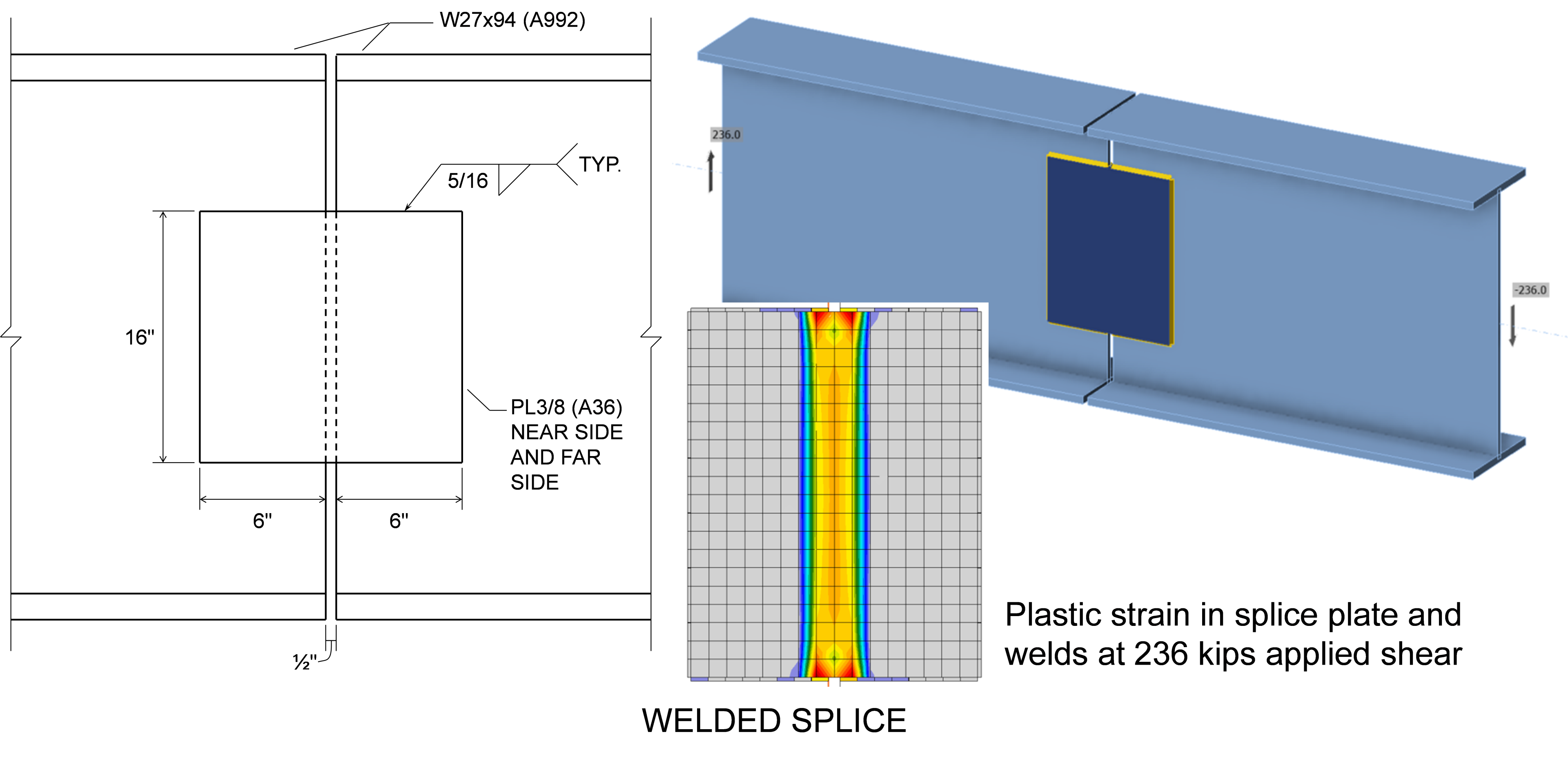
As an example of the combined result of the differences between the AISC Specification equations and IDEA StatiCa, consider the two beam splice connections shown in the figures below. For both, two W27×94 beams made of A992 steel are connected by splice plates on either side of the web. The splice plates are 3/8 in. thick and made of A36 steel.
The welded connection is controlled by shear yielding of the splice plates. The design strength for the plates is ϕRn = ϕ0.6FyAgv = (1.0)0.6(36 ksi)(2 × 3/8 in. × 16 in.) = 259 kips. In IDEA StatiCa, the splice plates reach a plastic strain of 5% when subject to a shear load of 236 kips. The difference in strengths is mostly due to the use of ϕ = 1.0 in the AISC Specification equations and a reduction of 0.9 on the yield stress in IDEA StatiCa.
The bolted connection is controlled by shear rupture of the splice plates. The design strength for the plates is ϕRn = 210 kips. In IDEA StatiCa, the splice plates reach a plastic strain of 5% when subject to a shear load of 213 kips, nearly the same as the design strength according to the AISC Specification, indicating that the differences counteract each other and result in a safe design.

Yielding Under Combined Actions
Members and connecting elements are often subject to multiple actions simultaneously, including axial force, bending moment, shear, and torsion. AISC Specification Section J4 does not provide specific requirements for connecting elements subject to combined actions. However, AISC Manual Part 9 describes several approaches for assessing connecting elements subject to combined actions. One approach is to superimpose stresses calculated based on elastic beam theory and use a first yield criterion. Another approach is to use interaction equations that approximate the limit of plastic strength. One such equation that applies to rectangular members under in-plane loading is AISC Manual Equation 9-1.
\[ \frac{M_r}{M_c} + \left ( \frac{P_r}{P_c} \right )^2 + \left ( \frac{V_r}{V_c} \right )^4 \le 1.0 \]
where Mr, Pr, and Vr are the required flexural, axial, and shear strengths, respectively; and Mc, Pc, and Vc are the available flexural, axial, and shear strengths, respectively.
Dowswell (2015) presented a more general equation for rectangular members under in-plane and out-of-plate loading.
\[ \left ( \frac{P_r}{P_c} \right )^2 + \left ( \frac{T_r}{T_c} \right )^2 + \left ( \frac{V_r}{V_c} \right )^4 + \left ( \left ( \frac{M_{rx}}{M_{cx}} \right )^{1.7} + \left ( \frac{M_{ry}}{M_{cy}} \right )^{1.7} \right )^{0.59} \le 1.0 \]
where Tr, Mrx, and Mry are the required torsional, major-axis flexural, and minor-axis flexural strengths, respectively; and Tc, Mcx, and Mcy are available torsional, major-axis flexural, and minor-axis flexural strengths, respectively.
In IDEA StatiCa, connecting elements are modeled with shell finite elements that are assigned a multi-axial plasticity material model that uses the von Mises yield criterion (use of the von Mises yield criterion is also described in AISC Manual Part 9). As load is applied in the model, the individual shell elements experience general states of stress which are evaluated using the criterion to determine if yielding has occurred. If yielding occurs, the stiffness of the material is reduced to 1/1000 of the initial stiffness and the analysis continues.
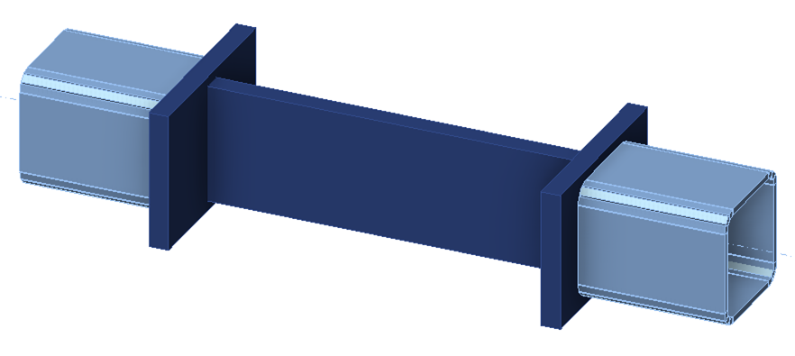
To illustrate the differences between strengths computed using interaction equations and IDEA StatiCa, consider the connection shown below. The middle “test” plate has a thickness of 1 in., height of 6 in., a length of 10 in., and is made of A36 steel. Both the connecting plates and hollow section members were selected to be strong and stiff. Analyses were performed subjecting the test plate to biaxial loading, consisting of axial tension and bending moment about the major- and minor-axes to determine maximum permitted applied loads (i.e., the loads which cause 5% plastic strain in the test plate). For these analyses, the geometric nonlinear (GMNA) option was turned off in the code setup. Also, the maximal size of elements was changed to 0.25 in. and the minimal size of elements was changed to 0.10 in. to create a finer mesh and capture the stress distribution more accurately.
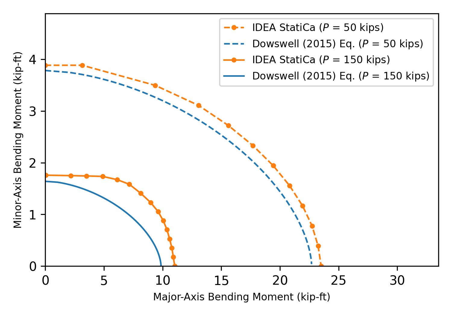
Results of the IDEA StatiCa analyses are shown in the figure below. Interaction diagrams based on the Dowswell (2015) equation are also shown in the figure. Available strengths used for the calculated interaction diagrams are Pc = ϕPn = 194.4 kips, Mcx = ϕMnx = 24.3 kip-ft, and Mcy = ϕMny = 4.05 kip-ft. Differences are seen between the IDEA StatiCa results and those from the interaction equation, including when only one action is applied. The causes of the differences under a single action are described in the entries on flexural yielding and tensile yielding. The differences between IDEA StatiCa and the approximate equation for combined actions are greater, but the IDEA StatiCa results show clear interaction effects.
Block Shear Rupture
Block shear rupture is a combined tension and shear failure in which a block of material is torn away from a member or connecting element. The available strength for the limit state of block shear rupture is defined in AISC Specification Section J4.3. As with the limit state of tensile rupture, the limit state of block shear rupture is not directly evaluated in IDEA StatiCa. It is captured by limiting the amount of plastic strain any component can experience to a maximum of 5% (the user can change this limit). Key differences between the traditional calculations and IDEA StatiCa result from the stress-strain relationship used in IDEA StatiCa. Only minimal post-yield hardening is included (i.e., stresses do not reach Fu), and the yield stress is reduced by 0.9 for LRFD (i.e., not ϕ = 0.75 as specified for block shear rupture).
A comparison between traditional calculations and IDEA StatiCa for the limit state of block shear rupture in bolted connections is presented in this article. The results of comparison show that strength from IDEA StatiCa can be greater than that according to the AISC Specification for some cases, especially if the ratio of tensile strength to yield strength (Fu/Fy) is relatively low. However, researchers have identified that the provisions of the AISC Specification can be conservative in comparison to experimental results. The block shear rupture strength from IDEA StatiCa was found to be accurate or conservative in comparison to the Canadian standard (CSA S16) and an alternative design equation proposed by researchers.
Strength for the limit state of block shear rupture in IDEA StatiCa can vary based on the shear force transfer type of the bolts. In IDEA StatiCa, forces are transferred from one plate to another over a larger area for slip-critical connections than for bearing-type connections. The larger spread of transfer forces, while physically representative of load transfer by friction, can lead to different block shear rupture failure paths and increased strength. For most connections, slip strength is less than block shear rupture strength. However, since slip-critical connections are required to be designed for the limit states of bearing-type connections in addition to slip (AISC Specification Section J3.9), it is recommended that slip-critical connections be analyzed twice in IDEA StatiCa: once as a slip-critical connection (i.e., with shear force transfer type set to “Friction”) and again as a bearing type connection (i.e., with shear force transfer type set to “Bearing – tension/shear interaction”).
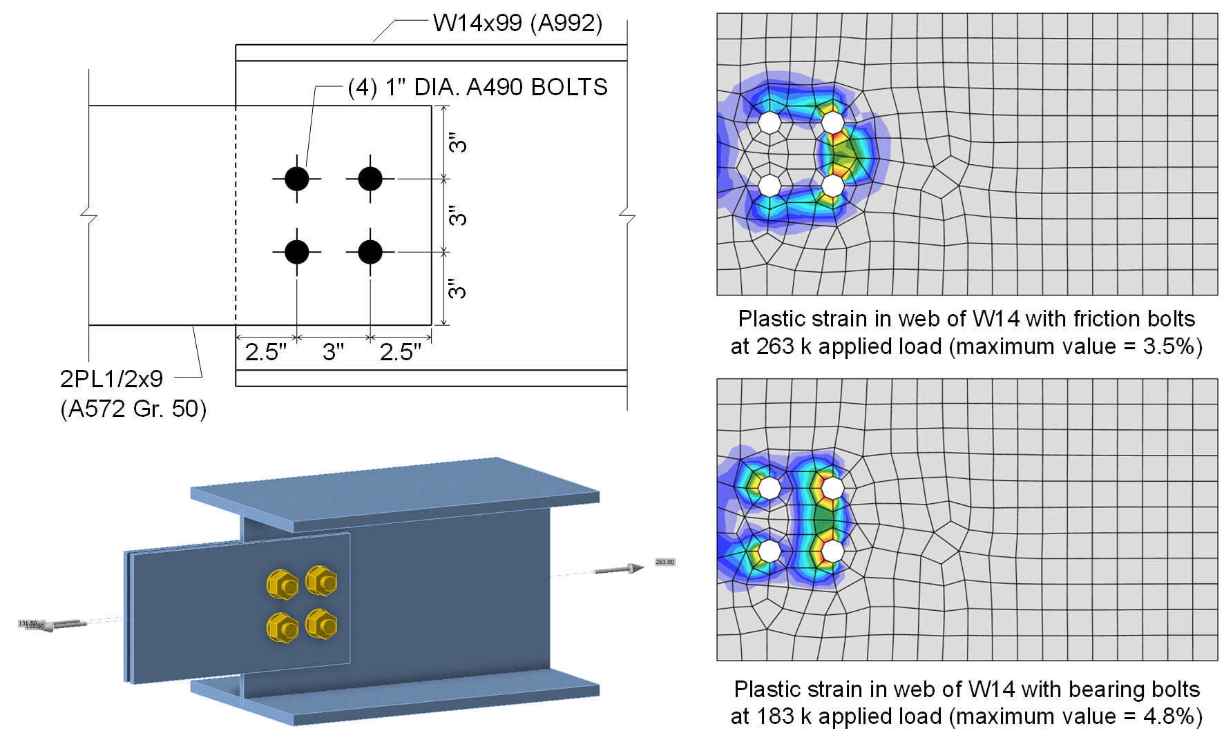
To illustrate this effect, consider the connection shown below between a W14x99 (A992) tension member and two plates. The connection is made with (4) 1 in. diameter A490 bolts in standard holes and Class B surfaces. The design strength of this connection for the limit state of slip is \(\phi R_n = 289\textrm{ kips}\), however, block shear rupture controls the strength of the connection with a design strength of \(\phi R_n = 148 \textrm{ kips}\). When modeled in IDEA StatiCa and the shear force transfer type of the bolts is set to “Friction”, applied loads of up to 263 kips can be applied before the utilization of the bolts reaches 100%. The difference between this strength and the 289-kip design strength for the limit state of slip is because tension in the bolts develops in the model and is conservatively treated as an applied tension in IDEA StatiCa. At 263 kips of applied tension and using “Friction” bolts, the plastic strain in the web is 3.5%, below the 5% limit. When the shear force transfer type for the bolts is set to “Bearing – tension/shear interaction” the maximum applied load decreases to 183 kips with plastic strain in the web controlling. The difference between this strength and the 148-kip design strength for the limit state of block shear rupture is predominantly conservatism in the AISC Specification equation for block shear rupture as described in this article. According to the Canadian standard (CSA S16), the design strength of this connection for the limit state of block shear rupture is 181 kips, approximately equal to the strength from IDEA StatiCa. The figure below shows the plastic strain in the web at the maximum applied load for each shear force transfer type. The distributions of plastic strain are clearly different and demonstrate the larger spread of transfer forces for “Friction” bolts in IDEA StatiCa. Additional discussion can be found in the entry on Slip.
Flexural Yielding
The nominal strength for flexural yielding is defined in AISC Specification (2022) Chapter F for flexural members and Section J4.5 for connecting elements. The nominal strength for the limit state of flexural yielding is generally taken as the specified minimum yield stress, Fy, times the plastic section modulus, Z. In IDEA StatiCa, instead of limiting the required strength to be no more than the available strength (e.g., Mu ≤ ϕMn), members and connecting elements are modeled with shell elements that are assigned a nonlinear stress-strain relationship consisting of a linear elastic region and a linear plastic region, and the plastic strain is limited to 5%.
Modeling members and connecting elements as shell elements results in some simplifications of the physical geometry. For example, shell elements only represent rectangular components thus, fillets are neglected. Additionally, since shell elements are connected at nodes located at the center of thickness there is some overlap at joints of cross-sectional elements. The figure below shows the simplifications for a wide flange shape.
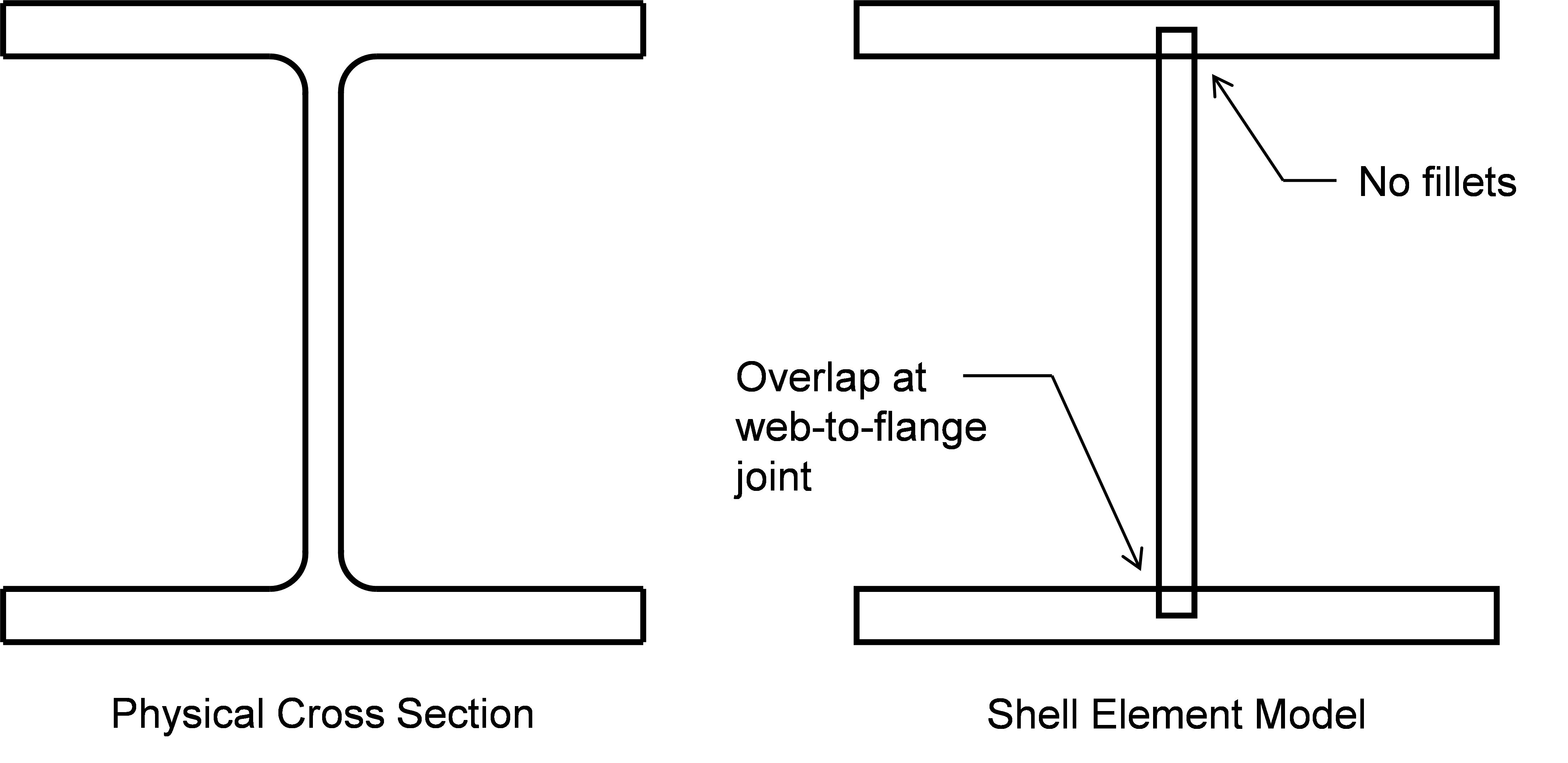
Wide flange shape as modeled in IDEA StatiCa
For a W24x176, the plastic section modulus about the major axis (x axis) listed in the AISC Steel Construction Manual (2023) Table 1-1 is 511 in.3. The plastic section modulus about the major axis of the cross-section formed by the shell elements (with cross-sectional dimensions determined from AISC Manual Table 1-1) is calculated as follows:
\[\frac{t_w(d-t_f)^2}{4}+2b_f t_f \left ( \frac{d-t_f}{2} \right ) = \frac{0.75 \textrm{ in.}(25.2 \textrm{ in.}-1.34\textrm{ in.})^2}{4}+2(12.9\textrm{ in.}) (1.34\textrm{ in.}) \left ( \frac{25.2\textrm{ in.}-1.34\textrm{ in.}}{2} \right ) = 519.2 \textrm{ in.}^3\]
This is 1.6% greater than the plastic section modulus listed in the AISC Manual table.
The stress distribution at the plastic strain limit in IDEA StatiCa will also be different than the idealized stress distribution used to compute Mp. Unlike the idealized stress distribution, the stresses will be lower than Fy near the neutral axis since the plastic strain limit will be reached at a finite curvature. Also, the stresses will be greater than Fy at the extreme fibers of the cross section because a small amount of post-yield hardening is assumed in the stress-strain relationship in IDEA StatiCa.
The overall effect of these minor differences can be observed in a simple splice connection between two W24x176 (ASTM A992) steel shapes. The splice is butt welded (e.g., CJP) and loaded in major axis bending. The design strength of the wide flange according to the AISC Specification (2022) with resistance factor, ϕ = 0.9, is 0.9 × 50 ksi × 511 in.3 = 1916.3 kip-ft. The maximum moment that can be applied to the connection in IDEA StatiCa (version 23.0) is 2000.7 kip-ft., 4.4% greater than the design strength as calculated per the AISC Specification. The plastic strain distribution at the limit is shown in the figure below. As expected, the top and bottom flanges have yielded, but web at the neutral axis remains elastic.
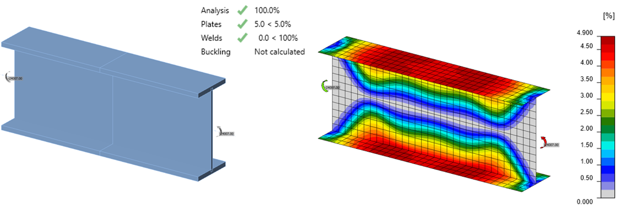
Plastic strain distribution for a W24x176 flexural member at the 5% plastic strain limit
The relationship between applied moment and maximum plastic strain is shown in the figure below. The design flexural strength calculated using the plastic section modulus from the AISC Manual is shown as ϕMp (Manual). The design flexural strength calculated using the plastic section modulus calculated as shown above based on the representation of the section in IDEA StatiCa is shown as ϕMp (IDEA).
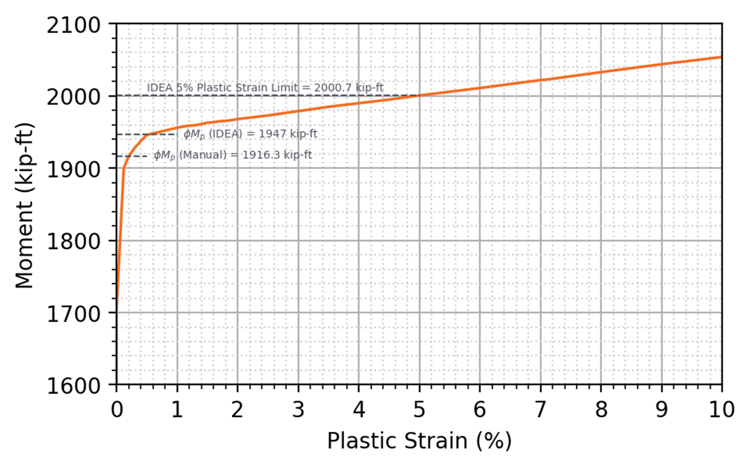
Applied moment vs plastic strain for a W24x176 flexural member
For a wide flange beam, most of the flexural resistance is captured by the in-plane behavior of the shell elements. The out-of-plane behavior of the shell elements can be evaluated through an investigation of plate bending.
For a plate (ASTM A36, Fy = 36 ksi) of width, b = 10 in. and thickness, t = 0.5 in., the plastic section modulus for out-of-plane bending is calculated as Z = bt2/4 = 0.625 in.3, and the design strength, ϕMp, with resistance factor, ϕ = 0.9 is calculated as 0.9 x 36 ksi x 0.625 in.3 = 20.25 kip-in. The geometric simplifications described above for a wide flange section don’t apply to a simple rectangular plate but differences in the stress distribution remain. The maximum moment that can be applied to the plate in IDEA StatiCa (version 23.0) is 19.66 kip-in., 2.9% less than the design strength as calculated per the AISC Specification. The plastic strain distribution for the plate loaded in minor axis bending and a plot of applied moment vs plastic strain are presented in the figures below.
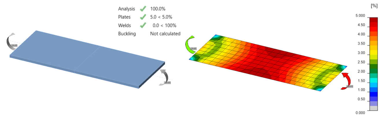
Plastic strain distribution for plate out-of-plane bending at the 5% plastic strain limit

Applied moment vs plastic strain for a plate loaded in minor axis bending
Flexural Rupture
Flexural rupture is among the limit states identified for affected elements of members and connecting elements in flexure in AISC Specification Section J4.5. Flexural rupture can occur when a moment is applied to a cross-section with material removed, such as bolt holes. AISC Specification Chapter J does not define the available strength for the limit state of flexural rupture. AISC Specification Section F13.1 addresses flexural rupture for members with bolt holes in the tension flange, and guidance is provided for flexural rupture of affected and connecting elements in Part 9 of the AISC Manual. Specifically, AISC Manual Equation 9-8 defines the nominal strength for flexural rupture as the product of the specified minimum tensile strength and the net plastic section modulus of the affected or connecting element. The AISC Manual further defines the resistance factor as \(\phi=0.75\) and safety factor as \(\Omega = 2.00\) for flexural rupture.
As with the limit state of tensile rupture, IDEA StatiCa does not evaluate strength equations for flexural rupture. Instead, the limit state of flexural rupture is evaluated using the plastic strain limit. Thus, like for tensile rupture, differences arise because the stress strain relationship used in IDEA StatiCa has minimal strain hardening past yield whereas the design equation uses the tensile strength of the material and because IDEA StatiCa reduces the stress at yielding by a factor of 0.9 (for LRFD) whereas a resistance factor of 0.75 is used for flexural rupture. Additional differences, specific to flexural rupture, result from the use of a plastic section modulus in the design equation, which assumes a uniform stress in either tension or compression. In IDEA StatiCa, stresses are an analysis result and not necessarily uniform.
To examine the net effect of these differences, consider the splice plates tested by Mohr and Murray (2008). They tested 14 specimens altogether; the six tests of the first series with three different bolt patterns are investigated here. The plates were installed between two W27x84 beams. The whole assembly was loaded in four-point bending, subjecting the plate to pure flexure. The dimensions of the largest plates, those with 7 bolts in each vertical row, are shown below. Tests were also performed with 5 and 3 bolts in each vertical row with similar dimensions. The measured yield strength of the plates was Fy = 49.5 ksi, the measured tensile strength of the plates was Fu = 72.1 ksi, and the measured thickness of the plates was t = 0.370 in.
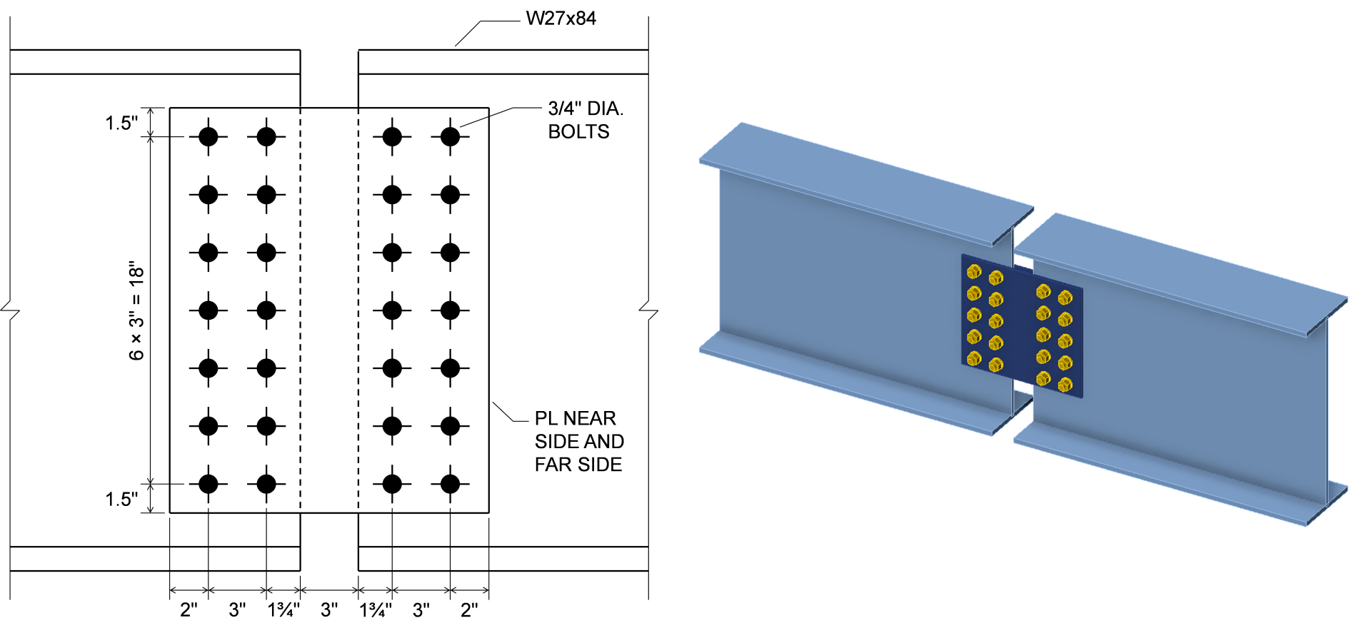
The design strength, \(\phi M_n\), of the plates was computed according to the AISC Specification for the limit state of flexural yielding and the AISC Manual for the limit state of flexural rupture. Measured material and geometric properties were used in these calculations and resistance factors were applied. IDEA StatiCa models of the three connections were also built using measured material and geometric properties of the plates. Resistance factors remained as their default values. Properties of the beams and bolts were increased from nominal values to ensure the failure mode matched that of the experiment. The maximum permitted applied moment from IDEA StatiCa, MIDEA, was determined iteratively. The results of these calculations are shown in the figure below along with the experimental strength, Mexp. The experimental strength was taken as the average of the reported strengths for the two specimens of each bolt pattern. The moments in the figure are for each plate noting that there were two plates for each specimen, one on each side of the beams.
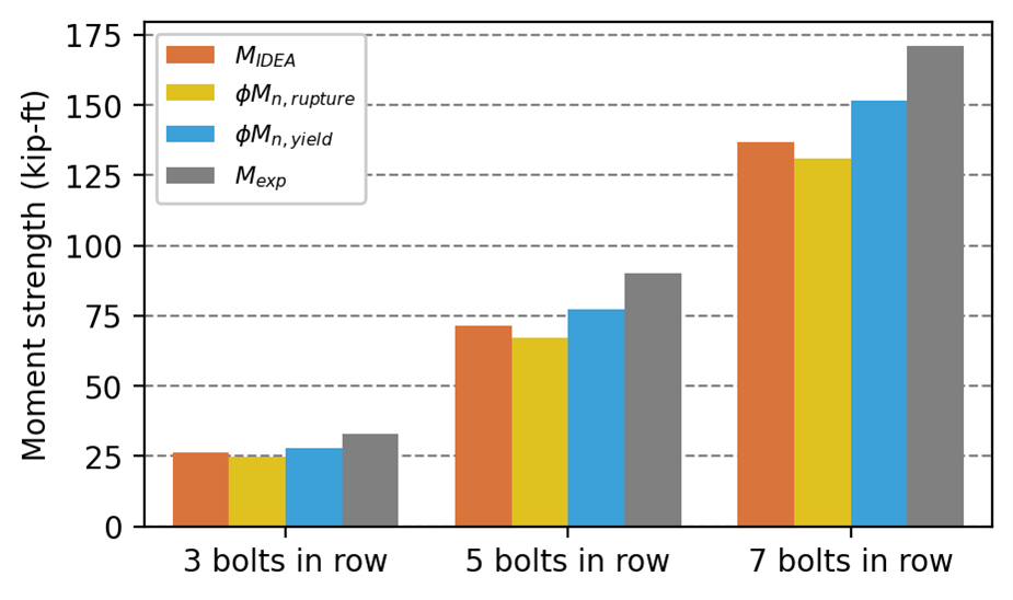
In the physical experiments, all the specimens failed by flexural rupture. Flexural rupture also controls the moment strength of the plates since \(\phi M_{n,rupture} < \phi M_{n,yield}\). IDEA StatiCa, however, does not clearly distinguish between these two limit states; both are evaluated using the 5% plastic strain limit. The plastic strain in the plates at the maximum permitted applied load is shown for the cases with 7 and 3 bolts in each vertical row below.


The maximum permitted applied moment from IDEA StatiCa, MIDEA, is approximately 5% greater than \(\phi M_{n,rupture}\) for these cases, a slightly unconservative result in comparison to the AISC Manual equation. However, MIDEA is approximately 20% lower than Mexp for these cases. While it is expected that MIDEA is less than Mexp since no reduction factor was applied to the experimental results, the difference indicates that there is a safety margin.
Concrete Crushing
At column bases bearing stresses are developed on concrete footings and foundations. AISC Specification (2022) Section J8 provides an equation for the strength of the concrete for the limit state of concrete crushing that is identical to the equivalent provisions in ACI 318 (ACI 2019). The strength depends on the area of steel bearing on a concrete support, the geometry of the concrete support, and the specified compressive strength of concrete.
IDEA StatiCa uses these provisions to evaluate concrete crushing. However, some differences between IDEA StatiCa and traditional hand calculations in the evaluation of concrete crushing arise because of differences in the underlying analysis approach. In hand calculations it is common to assume that the bearing stress is unform over the contact area. In IDEA StatiCa, the stiffness of the concrete footing, the stiffness of the column base, and contact are explicitly modeled resulting in a more physically realistic, non-unform distribution of bearing stress. The bearing area in IDEA StatiCa is computed as the area of steel that is in contact with the concrete and with a bearing stress greater than a cut-off value (the stress cut-off is defined as a ratio to the peak bearing stress with the ratio selectable in the code setup). This can result in a relatively complex shape for the bearing area as shown in the figure below. Nonetheless, the total bearing force, bearing area, and geometrically similar area in the concrete support are computed for use in the code equation.
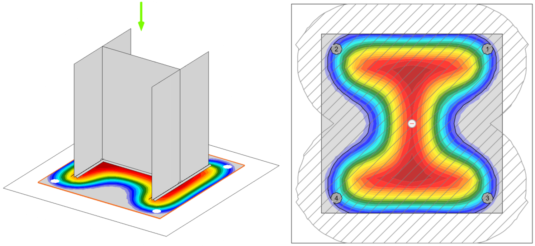
Three-dimensional view (left) and plan view (right) of stress in concrete at the steel-concrete interface of a concentrically loaded base plate connection. The boundary of the bearing area (A1 in AISC Specification Section J8) is shown as a solid black line in the plan view. Note the irregular shape that follows the stress contours and the anchor rod holes. The concrete supporting surface (A2 in AISC Specification Section J8) is shown as the hatched region of the plan view and is similarly irregular.
Additional information can be found in these articles:
- https://www.ideastatica.com/support-center/general-theoretical-background#Structural_model_of_a_concrete_block
- https://www.ideastatica.com/support-center/check-of-components-according-to-aisc
- https://www.ideastatica.com/support-center/check-of-concrete-blocks-according-to-aisc
- https://www.ideastatica.com/support-center/base-plate-connections-aisc
Flange Local Bending
Flange local bending is among the limit states that apply to concentrated forces applied normal to the flange of wide-flange sections and similar built-up shapes. It applies only to tensile concentrated forces. The nominal strength for the limit state of flange local bending is defined in AISC Specification (2022) Section J10.1.
As described in the commentary on Section J10.1, the limit state of flange local bending was originally intended to prevent weld fracture which could occur prematurely because of uneven demands due to flange deformation. However, more recent tests have shown that weld fracture does not occur when flange local bending strength is exceeded, but rather that the flange local bending strength represents a lower bound at which flange deformation could lead to premature flange local buckling or be detrimental to other aspects of member performance. The commentary further notes that while flange deformations can also occur under compressive forces, the AISC Specification does not require flange local bending be checked for compressive forces because it is customary to perform the check for tensile forces only.
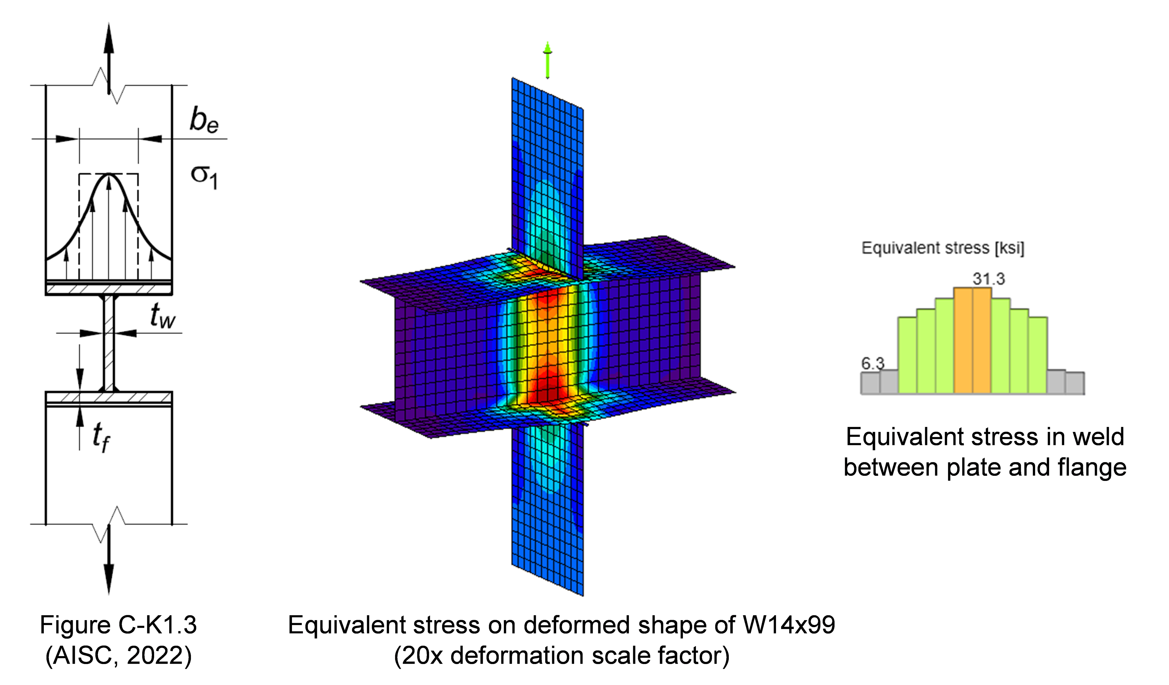
As shown in the figure above, both the uneven stress distribution and flange deformations are explicitly modeled in IDEA StatiCa. Each weld segment is checked independently for strength. Cases like shown in the figure above were examined in the calibration and subsequent validation and verification of the weld model in IDEA StatiCa. However, for shapes other than HSS, local flange deformations are not checked against a limit, their effect on member performance is not evaluated, and their magnitude cannot be directly obtained from the model. As a result, the limit state of flange local bending is not evaluated in IDEA StatiCa. Where the flange local bending controls traditional calculations, significantly higher strengths can be obtained from IDEA StatiCa. Where flange deformations are a concern, it is recommended to evaluate the limit state outside of IDEA StatiCa.
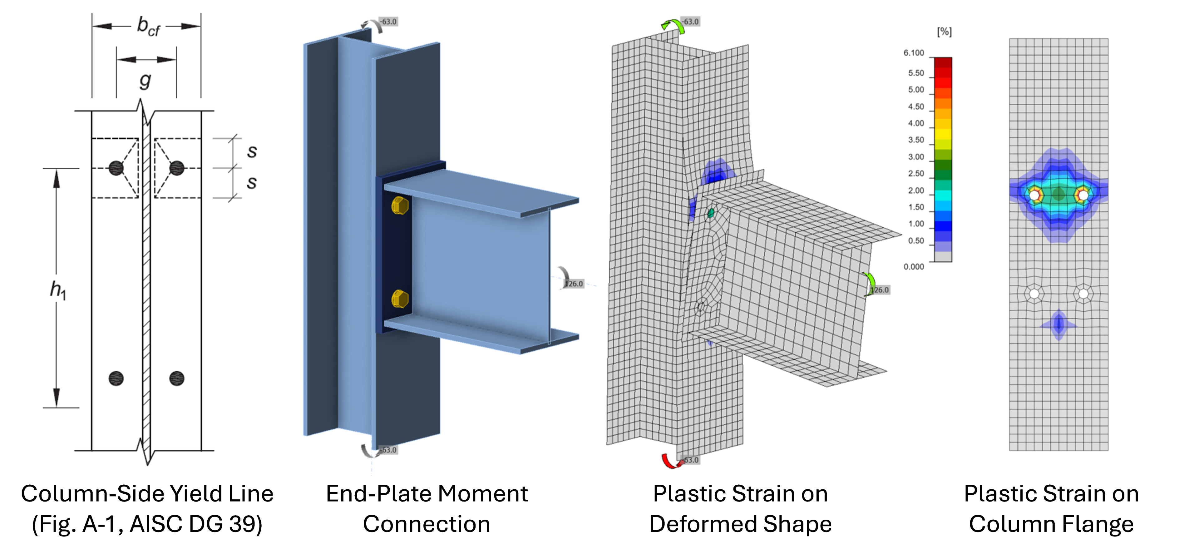
Note that flexural yielding of flanges in bolted connections is considered a separate limit state. In traditional calculations, the available strength is typically determined using yield line theory as described by Dowswell (2011) for general connections or Eatherton and Murray (2023) for end-plate moment connections. IDEA StatiCa captures this limit state through explicit modeling of the flange as shown in the figure below.
Web Local Yielding
Web local yielding is among the limit states that apply to concentrated forces applied normal to the flange of wide-flange sections and similar built-up shapes. The nominal strength equations for web local yielding in AISC Specification Section J10.2 are based on yield of the web over a length equal to the length of bearing plus an assumed spread of the force through the flange. While yielding of the web is modeled explicitly in IDEA StatiCa, several features of the design equations are not. The equations assume a stress gradient of 2.5:1 through the flange and the fillet of rolled shapes. In IDEA StatiCa, the flange is modeled with shell elements and the fillet is neglected, thus the spread of forces depends largely on the constraints between the flange and web. There are two separate equations in AISC Specification Section J10.2 for web local yielding depending on the distance of the force away from the member ends. In IDEA StatiCa, reduction in strength due to proximity to the member end is captured by directly modeling the member. A resistance factor of ϕ = 1.00 and safety factor of Ω = 1.50 apply to the limit state of web local yielding. IDEA StatiCa does not utilize these factors and instead reduces the yield point by a factor of 0.9 for LRFD or by dividing by 1.67 for ASD based on the typical resistance factor and safety factor for yielding.
The overall effect of these differences has been investigated for beam-over-column connections in this article and generic concentrated forces in this report.
Web Compression Buckling
Web compression buckling is among the limit states that apply to concentrated forces applied normal to the flange of wide-flange sections and similar built-up shapes. It applies when a pair of forces compress the web from both flanges at the same location along the length of the member. AISC Specification Section J10.5 provides an equation for the nominal strength for web compression buckling. The equation is based on the elastic buckling strength of a simply supported plate subjected to equal and opposite concentrated forces.
In IDEA StatiCa, design for web compression buckling can be accomplished by ensuring the elastic critical buckling load is sufficiently large (see discussion in the entry on Compressive Yielding and Buckling). Through comparisons to geometric and material nonlinear analysis with imperfections included (GMNIA) an elastic critical buckling load ratio of 3 was determined to be an appropriate lower limit.
Web Panel-Zone Shear Yielding
The available strength for the limit state of panel-zone shear yielding of wide-flange and similar built-up shapes is defined in AISC Specification Section J10.6. Four different equations are provided in this section for the nominal strength. One pair of equations is provided for when the effect of inelastic panel-zone deformation on frame stability is not accounted for in the analysis and another pair for when it is. The first pair of equations limits panel-zone behavior to the elastic range. The second pair of equations provides greater strength; however, plastic deformation of the panel-zone is necessary to achieve greater strength. The additional deformations can significantly increase overall frame deformations and second-order effects. If the potential for inelastic panel-zone deformation is not accounted for in the calculation of member and connection required strengths, then AISC Specification Section J10.6 requires panel-zone behavior to be limited to the elastic range.
In IDEA StatiCa, panel-zone shear yielding is modeled explicitly with nonlinear shell elements and is limited by a plastic strain limit. The limit state of panel-zone shear yielding was explored for extended end plate moment connections in this article and for bolted flange plate moment connections in this article. Using the default plastic strain limit of 5%, the strength from IDEA StatiCa exceeds that from the AISC Specification for when the effect of inelastic panel-zone deformation on frame stability is not accounted for in the analysis. However, reducing the plastic strain limit to a small value (e.g., 0.1%) in IDEA StatiCa enforces essentially elastic behavior and results in strengths that are accurate in comparison to the AISC Specification equations for when the effect of inelastic panel-zone deformation on frame stability is not accounted for in the analysis.
Engineers should know if the effect of inelastic panel-zone deformation on frame stability was accounted for in the analysis to determine required strengths (i.e., not the IDEA StatiCa analysis). And, if it was not, they should limit panel-zone behavior to be essentially elastic.
Connections to HSS Members
AISC Specification (2022) Chapter K includes additional requirements, beyond those of Chapter J, that apply to connections to HSS members and box sections that behave like HSS members. Chapter K is organized by connection type and the requirements are often accompanied by limits of applicability. However, Chapter K does not prohibit the use of connections of other configurations or those outside the limits of applicability.
The limit states described in the tables of Chapter K are evaluated in IDEA StatiCa by explicit modeling and the 5% plastic strain limit. The effects of parameters defined in Section K1, including the effective width for connections to rectangular HSS to account for uneven stress distributions, the chord-stress interaction parameter, and end distance are also modeled explicitly. To increase accuracy, geometric nonlinearity is included in the model by default when a hollow cross-section is used as a bearing member.
The commentary on Chapter K states “When inelastic finite element analysis is used, peak strains in the thick shell (T × T × T) elements should not exceed 0.02/T at the nominal capacity, where T is the thickness in inches.” Neglecting the difference between strain and plastic strain, the limiting value of this recommendation is greater than the 5% used by IDEA StatiCa when the thickness is less than 0.4 in. While the strain limit in the commentary recommendation is more restrictive than the default limit in IDEA StatiCa for thicker tubes, the 5% plastic strain limit is more widely recognized as an acceptable limit for strength design including by the Steel Tube Institute.
Chapter K is based on strength limit states only. As a result, large deformations can occur in connections that meet the requirements of Chapter K. Nonetheless, local out-of-plane deformation of HSS members is checked in IDEA StatiCa against a limit of 3% of the smallest transverse dimension of the cross-section (i.e., diameter or width) based on the requirements of other standards.
As the provisions of Chapter K are based largely on international research and the work of international committees, verifications to other standards are generally informative to US practice. Several verification studies for connections to HSS members are available on the IDEA StatiCa website, including for connections between rectangular hollow sections, circular hollow sections, plate and rectangular hollow sections, and plate and circular hollow sections.
Design Considerations and Requirements
Tasarım Esasları
AISC Şartnamesine göre dayanım tasarımı, yük ve direnç faktörü tasarımı (LRFD) veya izin verilen dayanım tasarımı (ASD) hükümleriyle gerçekleştirilir. Bu iki yaklaşımın gerekli dayanımları ve mevcut dayanımları farklı olsa da nominal dayanımlar aynıdır ve nihai tasarımlar aynı olmasa da benzer olmalıdır.
| Dayanım Kriteri | Gerekli Dayanım | Mevcut Dayanım | Nominal Dayanım | |
| LRFD | \(R_u \le \phi R_n\) | Ru LRFD yük kombinasyonları kullanılarak hesaplanır (örn., 1.2D + 1.6L + 0.5Lr) | \(\phi\)Rn tasarım dayanımı olarak da adlandırılır (\(\phi\) bir direnç faktörüdür) | Rn |
| ASD | \(R_a \le R_n/\Omega\) | Ra ASD yük kombinasyonları kullanılarak hesaplanır (örn., D + L) | Rn/Ω izin verilen dayanım olarak da adlandırılır (Ω bir güvenlik faktörüdür) | Rn |
LRFD yük kombinasyonlarındaki daha büyük yük faktörleri nedeniyle LRFD için gerekli dayanımlar ASD'ye kıyasla daha büyüktür. Gerekli dayanımlar doğrusal olmayan analiz kullanılarak hesaplandığında ve doğrusal olmama düzeyi yükleme düzeyine bağlı olduğunda da gerekli dayanımlar arasında farklılıklar ortaya çıkabilir. Stabilite tasarımında bunu telafi etmek amacıyla AISC Şartnamesi, tüm yüke bağlı etkilerin LRFD yük kombinasyonlarına veya ASD yük kombinasyonlarının 1,6 katına karşılık gelen bir yükleme düzeyinde hesaplanmasını zorunlu kılmaktadır. IDEA StatiCa farklı bir yaklaşım izlemektedir. IDEA StatiCa'da kabuk elemanlar için akma gerilmesi, LRFD için 0,9Fy ve ASD için Fy/1,67 olarak alınmakta olup 0,9 ve 1,67 değerleri akma sınır durumları için tipik direnç faktörü ve güvenlik faktörüne karşılık gelmektedir. Çoğu durumda bu, izin verilen maksimum uygulanan yüklerin LRFD için ASD'ye kıyasla 1,5 kat daha büyük olmasıyla sonuçlanmakta ve AISC Şartnamesinin hükümleriyle uyumlu olmaktadır. Ancak IDEA StatiCa'da elastisite modülü ne LRFD ne de ASD için azaltılmamaktadır. Bu nedenle rijitlik ile dayanım oranı yaklaşımlar arasında farklılık göstermekte ve tasarımda bazı sonuçlara yol açmaktadır. Burkulma açısından, sınırlayıcı elastik burkulma yük oranı LRFD ile ASD arasında farklılık göstermektedir. Ayrıca bir birleşimin rijitliğinin dayanımını etkilediği durumlarda, örneğin uzun kaynaklı birleşimlerde, LRFD ile ASD arasındaki izin verilen maksimum uygulanan yük oranı 1,5'ten sapabilir. IDEA StatiCa'yı AISC Şartnamesiyle karşılaştıran doğrulama çalışmalarının büyük çoğunluğu LRFD için gerçekleştirilmiştir.
IDEA StatiCa, 2022 AISC Şartnamesinde tanımlandığı şekliyle ASD hükümlerini uygulamaktadır. 2022 AISC Şartnamesindeki ASD hükümleri, 9. baskı AISC El Kitabında yer alan (yaygın olarak "yeşil kitap" olarak anılan) 1989 AISC Şartnamesi gibi tarihi standartlardan farklıdır. ASD için tarihi hükümler elastik davranışa odaklanmış ve LRFD ile daha fazla farklılık içermiştir. ASD için mevcut hükümler, ortak nominal dayanım hesaplamaları da dahil olmak üzere LRFD ile daha tutarlıdır.
Yapısal Çelik Malzemeleri
AISC Specification Bölüm A3.1, yapısal çelik malzemeleri için gereksinimleri içermektedir. Bu bölümde, Tablo A3.1, tatmin edici performans geçmişine sahip olan ve AISC Specification hükümlerinde öngörüldüğü şekilde performans göstermesi beklenen belirli malzemeleri listelemektedir. Listelenen malzemeler, 80 ksi'ye kadar akma gerilmesine sahip haddelenmiş profiller ve 100 ksi'ye kadar akma gerilmesine sahip plakalar için olanları kapsamaktadır. Tablo A3.1'de listelenenlerin dışındaki malzemelerin kullanımı, sorumlu mühendis tarafından kabul edilebilir olduğuna karar verildiğinde izin verilmektedir. Malzemelerin uygunluğunu; kullanım amacı, enine yöndeki dayanım özellikleri, süneklik ve kaynaklanabilirlik dahil olmak üzere pek çok faktör etkileyebilir.
IDEA StatiCa'nın AISC Specification hükümlerine yönelik kapsamlı doğrulaması göz önünde bulundurulduğunda, Tablo A3.1'de listelenen malzemelerin yazılımda da öngörüldüğü şekilde performans göstereceği kabul edilebilir. Tablo A3.1'de listelenmeyen malzemelerin kullanımı yasaklanmamış olmakla birlikte, sorumlu mühendisinin takdirine bırakılmaktadır. AISC Specification Bölüm A3.1 şerhinde, malzemelerin uygunluğunu etkileyen faktörler ve uygunluğun değerlendirilmesine yönelik rehberlik hakkında tartışmaya yer verilmektedir.
Kaldırma Kuvveti Etkisi
Cıvatalı birleşimlerde, bağlantı elemanları arasındaki temas, çekme kuvvetlerini yalnızca uygulanan yüklerden kaynaklanan değerlerin ötesine taşıyabilir. Bu fenomen kaldırma kuvveti etkisi olarak bilinir ve yalnızca çekme cıvata kuvvetlerinin bulunduğu birleşimlerde meydana gelir. Cıvata kuvvetlerini artıran temas, bağlantı elemanının deformasyonu nedeniyle oluşur. Bu nedenle kaldırma kuvveti etkisi, hem cıvatalar hem de bağlantı elemanları için bir tasarım kriteri oluşturur.
Cıvataların ve bağlantı elemanlarının göreli rijitliği ve dayanımı davranışı belirler. Bağlantı elemanları cıvatalara göre rijit ise, bağlantı elemanları geri bükülme ve temas oluşturmaksızın deformasyon gösterir ve kaldırma kuvveti etkisi meydana gelmez. Bu durumda tasarımı cıvataların dayanımı belirler. Bağlantı elemanları cıvatalara göre zayıf ise, bağlantı elemanları akma yapar ve cıvatalara kaldırma kuvvetleri uygular; ancak bu durum aynı zamanda cıvatalardaki kuvveti de sınırlar. Bu durumda tasarımı bağlantı elemanlarının dayanımı belirler. Ara durumda ise tasarımı cıvataların ve bağlantı elemanlarının dayanımı eş zamanlı olarak belirler.
Tasarımda kaldırma kuvveti etkisinin göz önünde bulundurulmasına ilişkin yönlendirme, AISC Manual'ının 9. Bölümünde sunulmaktadır. AISC Manual'ında yer alan denklemler, T-profil ve sırt sırta köşebent gibi yaygın durumlar için geliştirilmiş ve deneysel verilerle doğrulanmıştır. IDEA StatiCa, belirli konfigürasyondan bağımsız olarak kaldırma kuvveti etkisinin analizde doğal biçimde yakalanması amacıyla temas dahil cıvataların ve bağlantı elemanlarının rijitliğini ve dayanımını açıkça modellemektedir. AISC Manual denklemleri ile IDEA StatiCa sonuçları arasında T-saplama birleşimleri için bir karşılaştırma yapılmıştır. Guide to Design Criteria for Bolted and Riveted Joints (Kulak ve diğerleri 1987) adlı kaynakta önerilen kaldırma kuvveti etkisi tasarım yaklaşımıyla benzer bir karşılaştırma da gerçekleştirilmiştir. Kaldırma kuvveti etkisi, çapraz birleşimler ve uzatılmış alın plakalı moment birleşimleri dahil diğer doğrulama örneklerinde de ele alınmaktadır.
Uzun Birleşimlerde Deformasyon Uyumluluğu
Uzun uçtan yüklenen birleşimlerde, bağlanan elemanlar arasındaki uzama farkı birleşimin uçlarında en büyük değere ulaşır. Sonuç olarak, uzun uçtan yüklenen birleşimlerde cıvata ve kaynaklardaki gerilme düzgün dağılmaz. Geleneksel hesaplarda düzgün gerilme dağılımı varsayımı yaygın olduğundan, AISC Şartnamesi uzun uçtan yüklenen kaynak uzunlukları ve cıvataların nominal kesme gerilmesi için azaltma katsayıları içermektedir. AISC Şartnamesi J2.2b Bölümü, kaynak uzunluğunun kaynak boyutunun 100 katını aşması durumunda azaltmalar dahil uçtan yüklenen köşe kaynaklarının etkin uzunluğunu tanımlamaktadır. AISC Şartnamesi Tablo J3.2'deki nominal kesme gerilmesi değerleri, uzunluk etkilerini dikkate almak için %10'luk bir azaltma içermekte olup bağlantı elemanı dizisi uzunluğu 38 inç'ten büyük olan uçtan yüklenen birleşimler için ek bir azaltma gerekmektedir.
IDEA StatiCa bu azaltmaları doğrudan uygulamaz. Bunun yerine, söz konusu azaltmalara yol açan temel davranış açıkça modellenir. IDEA StatiCa, cıvata, kaynak ve bağlantı elemanlarının rijitliğini modellediğinden, cıvata ve kaynaklardaki düzgün olmayan gerilme dağılımı doğal olarak ortaya çıkar. Cıvata ve kaynak segmentlerinin dayanımı ayrı ayrı değerlendirildiğinde, elde edilen birleşim dayanımı geleneksel hesaplardan elde edilen değerlerle karşılaştırılabilir düzeydedir. IDEA StatiCa ile uzun uçtan yüklenen birleşimler için geleneksel hesaplardan elde edilen sonuçlar arasındaki ayrıntılı karşılaştırma bu makalede sunulmaktadır.
Dışmerkezli Yüklü Cıvata ve Kaynak Gruplarında Deformasyon Uyumluluğu
Dışmerkezli yüklü gruplardaki cıvatalar ve kaynaklar, doğrudan kesme kuvvetine ek olarak oluşan momentten kaynaklanan ek kesme kuvvetine de maruz kalır. Cıvata veya kaynaklardaki sonuç gerilmesi, cıvatadan cıvataya ve kaynak segmentinden kaynak segmentine hem büyüklük hem de yön bakımından farklılık gösterir. AISC El Kitabı'nın 7. ve 8. Bölümlerinde açıklandığı üzere, mühendisler dışmerkezli yüklü cıvata veya kaynak gruplarını analiz etmek için anlık dönme merkezi yöntemini veya elastik yöntemi kullanabilir. Anlık dönme merkezi yöntemi kullanılarak yapılan hesaplamalar genellikle AISC El Kitabı'nda sunulan tablo değerleri kullanılarak gerçekleştirilir.
IDEA StatiCa'da, cıvata ve kaynak segmentlerinin gerekli dayanımı doğrusal olmayan analizin sonuçlarından belirlenir. Her cıvata ve kaynak segmenti ayrı ayrı modellenir ve denge koşulu sağlanır. Mevcut dayanımlar AISC Şartnamesine göre belirlenir.
Anlık dönme merkezi yöntemi de doğrusal olmayan analize dayanmaktadır; ancak anlık dönme merkezi yönteminin doğrusal olmayan analizi ile IDEA StatiCa arasında temel farklılıklar bulunmaktadır. Anlık dönme merkezi yönteminde bağlantı elemanlarının rijit olduğu varsayılır; bu durum IDEA StatiCa için geçerli değildir. Cıvata ve kaynakların kuvvet-deformasyon davranışı da iki yöntem arasında farklılık göstermektedir. IDEA StatiCa'da cıvata ve kaynaklar için kullanılan kuvvet-deformasyon davranışı bilineer olup teorik arka planda açıklanmaktadır.
Bu farklılıklar genel olarak, konsol plaka birleşimleri hakkındaki bu makalede gösterildiği üzere, IDEA StatiCa'dan benzer veya daha düşük dayanım değerleri elde edilmesiyle sonuçlanır. Dışmerkezli yüklü cıvata grupları için geleneksel hesaplamalar ile IDEA StatiCa arasındaki karşılaştırmalar, tek plakalı kesme birleşimleri hakkındaki bu makalede de ele alınmaktadır.
Bolts in Combination with Welds
Accurate strength prediction is more difficult when bolts and welds share load on a common faying surface. The lower ductility of welds in comparison to bolts can lead to brittle fracture before the full strength of the bolt is realized. AISC Specification Section J1.8 allows bolts and welds to be considered as sharing load only in certain circumstances.
According to Section J1.8, bolts can be considered as sharing load with welds only in the design of shear connections on a common faying surface where strain compatibility between the bolts and welds is considered. The section also describes a case with pretensioned high-strength bolts and longitudinal fillet welds where the nominal strength is permitted to be determined as the nominal slip strength plus the nominal weld strength. The bolts and welds must each support a specified proportion of the load and a resistance factor of ϕ = 0.75 or safety factor of Ω = 2.00 applies to the combined joint.
Strength checks for bolts and welds are independent in IDEA StatiCa with no special handling of when bolts and welds share load. Given the explicit modeling of the stiffness of bolts, welds, members, and connecting elements, strain compatibility is always considered in IDEA StatiCa. When bolts and welds share load, the required strength of each is based on their relative stiffness and the available strength is computed as usual. This is true even for tension connections; therefore, it is recommended to not model bolts and welds as sharing load for tension connections and instead only rely on one or the other.
To illustrate the differences between the method provided in AISC Specification Section J1.8 and IDEA StatiCa, consider the connection between plates subjected to tension shown below.
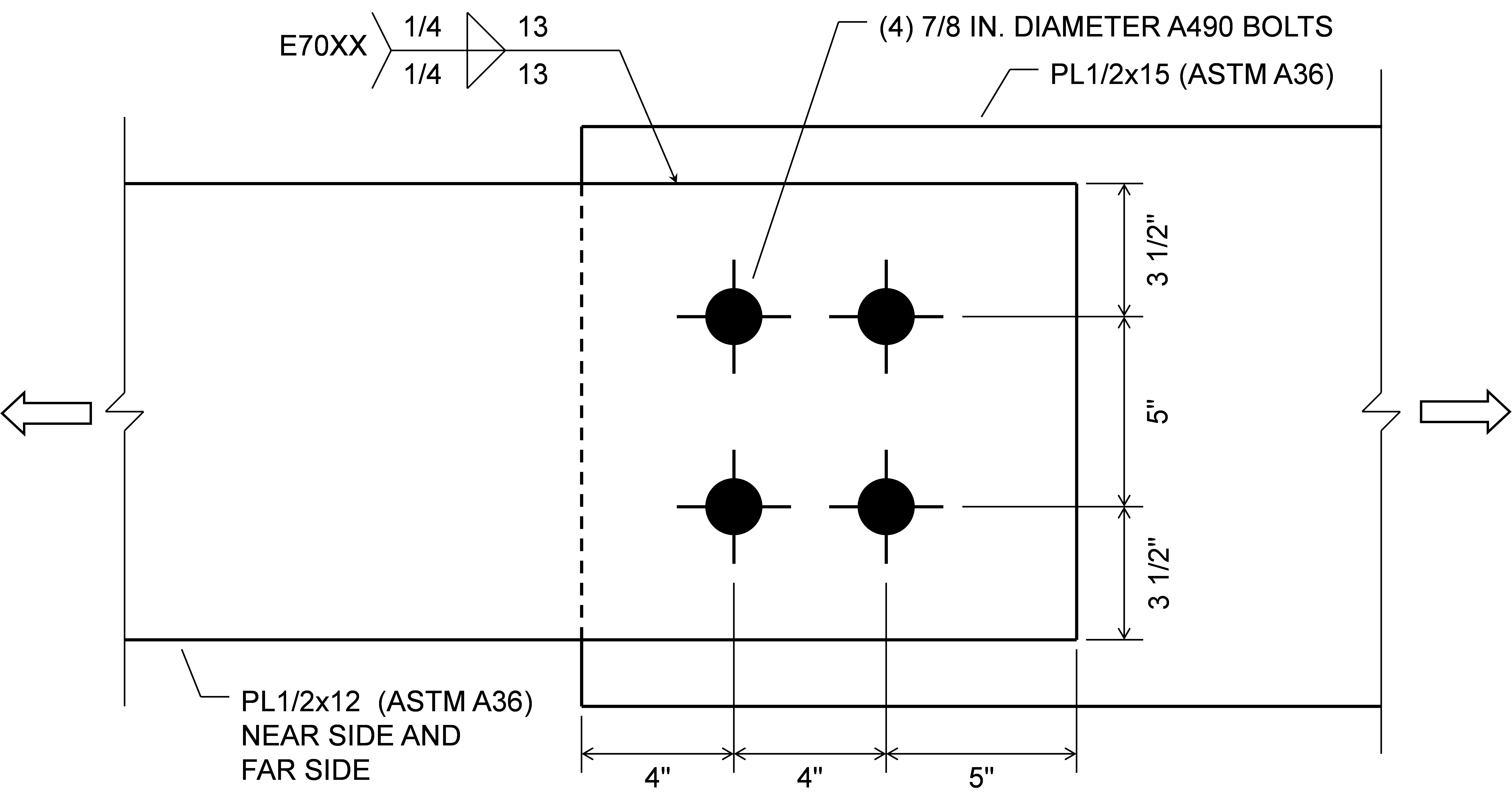
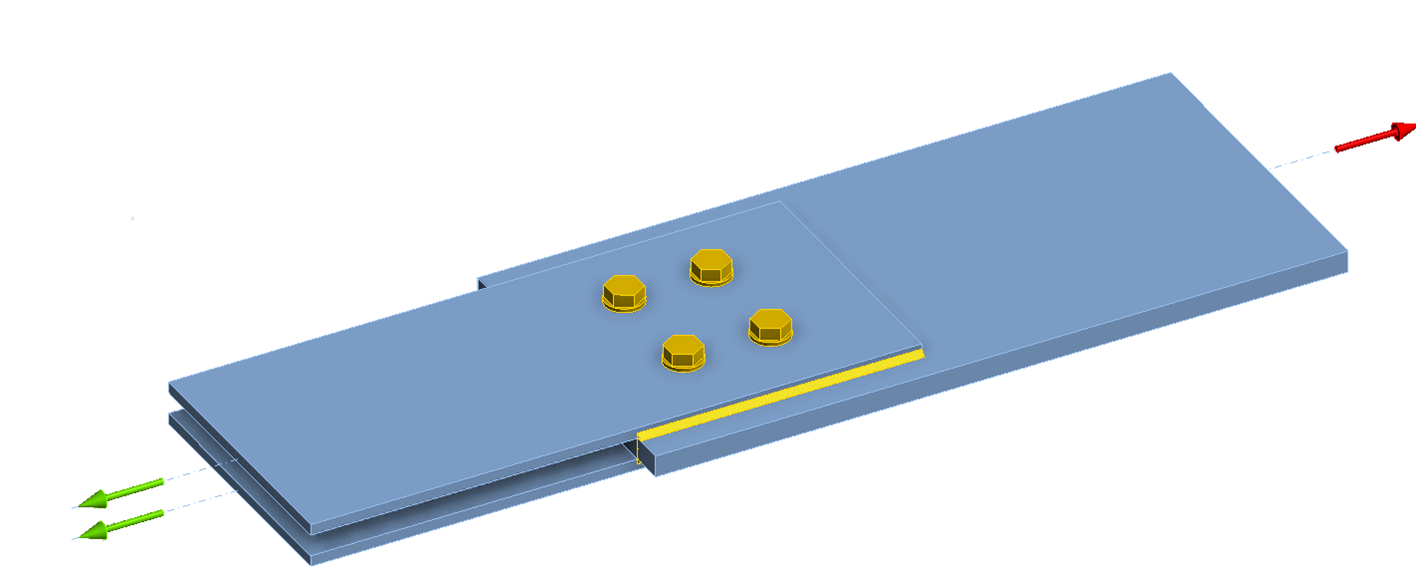
According to the AISC Specification, when the connection is designed as slip-critical, the design strength of the bolts alone is ϕRn = 133 kips (Rn = 133 kips). The design strength of the welds alone is ϕRn = 290 kips (Rn = 386 kips). When combining bolts and welds, the total connection strength is ϕRn = 0.75 (133 + 386) = 389 kips since all requirements in Section J1.8 to allow the summation of bolt and weld strengths are met.
In IDEA StatiCa, the maximum permitted applied tension is 126 kips when the bolts alone are modeled and 277 kips when the welds alone are modeled. The difference between the bolt strength in IDEA StatiCa and the 133-kips design strength is because tension in the bolts develops in the model and is conservatively treated as an applied tension in IDEA StatiCa (see entry on Slip). The difference between the weld strength in IDEA StatiCa and the 277-kips design strength is because of non-uniform demands along the length of the weld in IDEA StatiCa. When both bolts and welds are modeled, the maximum permitted applied tension is 394 kips, with both the bolts and welds showing 100% utilization. This value is closely comparable to the AISC Specification strength of 389 kips.
If the bolts are assumed to be bearing type, the design strength for the bolts according to the AISC Specification is ϕRn = 245 kips. While the AISC Specification permits bolts to be considered as sharing load with welds in shear connections, it does not provide a method to assess the strength when the bolts do not meet the requirements of a slip-critical connection. Therefore, it would be common to assess the strength of this connection as that of the welds alone or ϕRn = 290 kips.
In IDEA StatiCa, when the bolts are modeled as bearing bolts and the welds are not modeled, the maximum permitted applied tension matches the AISC Specification design strength of 245 kips. When the bolts are modeled as bearing bolts and the welds are modeled, the maximum permitted applied tension is 311 kips with weld strength being the controlling limit. This strength is only 12% more than the strength of the welds alone according to IDEA StatiCa. The minor increase in strength with the addition of bearing bolts is because the bolts are less stiff than the welds and thus do not attract much load before the welds reach 100% utilization.
Delik Boyutunun Etkisi
AISC Specification (2022) Bölüm J3.3, yapısal çelik birleşimlerde cıvatalar için standart, büyük boy, kısa uzun delikli ve uzun uzun delikli deliklerin kullanımını açıklamaktadır. Standart delikler IDEA StatiCa'da varsayılan olarak kullanılmaktadır. Büyük boy delikler, cıvata düzenlemesindeki delik çapı düzenlenerek elde edilebilir. Uzun delikler, plaka düzenleyicisinde plakalar için tanımlanabilir.
Delik boyutu, davranışın çeşitli yönlerini etkiler ve bazı tasarım gereksinimleri delik boyutuna bağlıdır.
- Cıvata delikleri için çıkarılan malzeme net alanı etkiler. Bu etki, IDEA StatiCa'da elemanlar ve bağlantı elemanları için kabuk eleman modelinin tanımlanması yoluyla açıkça ele alınmaktadır. Ancak, AISC Specification Bölüm B4.3b tarafından gerektirilen hasar için ek 1/16 inç otomatik olarak uygulanmamaktadır (bkz. Net Alan Belirlenmesi)
- Delik boyutu, yırtılma dayanımını belirlemek için kullanılan net mesafeyi etkiler. Bu etki, IDEA StatiCa'da bağlantılı malzemenin geometrisine ve bireysel cıvatadaki kuvvetin yönüne göre net mesafe hesaplanarak açıkça ele alınmaktadır.
- Büyük boy delikler, yataklamalı birleşimlerde kullanılamaz. IDEA StatiCa bu gereksinimi kontrol etmez ve büyük boy deliklerle yataklamalı kesme kuvveti aktarımına izin verir.
- Kayma sınır durumu için direnç faktörü, delik tipine bağlıdır. IDEA StatiCa, direnç faktörünü delik tipine göre otomatik olarak ayarlamaz. Direnç faktörü, Kod ayarlarında manuel olarak belirlenebilir.
Delik boyutu, cıvatanın yük-deformasyon tepkisini etkileyebilir. IDEA StatiCa'da kullanılan cıvata yük-deformasyon modeli delik boyutuna bağlı değildir, ancak uzun deliklerin uzun yönünde kesme aktarımının sıfır olduğu varsayılmaktadır.
Hadde Toleransı
Eleman uzunluğundaki değişkenlik, birleşim tasarımında kullanılan boyutlarda anlamlı farklılıklara yol açabilir. AISC Tasarım Örneklerindeki çeşitli hesaplamalarda, olası hadde toleransını dikkate almak için uzunluktan 1/4 inç tolerans düşülmektedir. IDEA StatiCa, olası hadde toleransını otomatik olarak hesaba katmaz; ancak birleşim, varsayılan tolerans değeri kullanılarak manuel olarak tanımlanarak olası hadde toleransı göz önünde bulundurulabilir.
Temas ve Sürtünme
Çelik fiziksel olarak çelikten geçemez; ancak sonlu elemanlar analizlerinde bu varsayılan davranıştır. Temas yüzeyleri, deformasyon sırasında malzemelerin üst üste gelmesini önlemek için tanımlanmalıdır. Yüzey-yüzey teması, cıvata grubu işlemleriyle otomatik olarak tanımlanır. Yüzey-yüzey teması, "Cıvata grubu/temas" işlemiyle de tanımlanabilir. Kenar-kenar teması veya kenar-yüzey teması ise "Genel kaynak veya temas" işlemiyle tanımlanabilir.
Tüm potansiyel temas yüzeyleri IDEA StatiCa tarafından otomatik olarak tanımlanmaz. Bu nedenle, kullanıcının birleşimin amaçlanan davranışını iyi anlaması ve birleşimin modellendiği ve amaçlandığı şekilde davrandığını doğrulamak için deforme olmuş şekli incelemesi önemlidir.
Temas yüklenmesi, birleşim uygun şekilde detaylandırılmış ve yüklemenin gerçekleşeceği şekilde yüzeyler dikkatlice hazırlanmışsa birleşimde kuvvet aktarımının verimli bir yolu olabilir (Muir 2015). Temas yüklenmesinin etkin olmasını sağlamak için özel detaylandırma gerektiğinden, kenar-kenar ve kenar-yüzey teması IDEA StatiCa'da otomatik olarak tanımlanmaz; ancak "Genel kaynak veya temas" işlemi kullanılarak manuel olarak tanımlanabilir. Cıvatalı kolon ekleri, elemanlar arasındaki kenar-kenar temasının tanımlanmasının cıvatalardaki talepleri azaltarak daha verimli bir birleşim sağladığı bir örnektir. Temas yüklenmesinin kullanımı, kolonlar ile taban plakaları arasındaki kaynaklarla birlikte de verimli olabilir. Kaynaklar, varsayılan olarak temas tanımlanmadan oluşturulur ve dolayısıyla basınç kuvvetleri için de kontrol edilir. Kaynak ve temas işlemlerinin birleştirilmesi, daha küçük kaynakların kullanılmasına olanak tanıyabilir. Kaynaklar rijittir ve temas ile birleştirildiğinde bile yük çeker; ancak basınç kuvvetlerinden kaynaklanan talepler, kaynak boyutu küçültülse bile kapasiteyi nadiren aşar.
Çelik-çelik temas yüzeylerindeki sürtünme, IDEA StatiCa'da muhafazakâr bir yaklaşımla ihmal edilir; yalnızca kesme kuvvetlerini sürtünme yoluyla aktaran cıvatalar (yani kayma kritik cıvatalar) bunun istisnasını oluşturur. Ön gerilmeli cıvataların sıkıştırma kuvveti sağladığı durumlarda sürtünmenin dikkate alınması, geleneksel hesaplamalar için de tipiktir. Ancak sürtünme nedeniyle IDEA StatiCa ile geleneksel hesaplamalar arasında bazı sonuç farklılıkları ortaya çıkabilir. Örneğin, AISC Specification Section J3.10, kayma kritik bir birleşimin birleşik çekme ve kesmeye maruz kalması durumunda kayma dayanımına uygulanacak bir azaltma faktörü tanımlar. Azaltma faktörü, birleşime uygulanan çekme yüküne dayanır. IDEA StatiCa, bir cıvatadaki çekme yükünün ne kadarının uygulanan yükten, ne kadarının kaldırma kuvveti gibi diğer kaynaklardan kaynaklandığını nicelendirme imkânına sahip değildir. Kaldırma kuvveti kayma kritik bir cıvataya çekme kuvveti uygularsa, IDEA StatiCa'da kayma dayanımı azaltılacaktır. Geleneksel hesaplamalara göre kayma dayanımı azaltılmayacaktır. Bu farkın ayrıntılı bir incelemesi, T-profil birleşimleri için bu makalede açıklanmaktadır.
Net Alan Belirleme
AISC Specification (2022) Bölüm B4.3b, çekme veya kesmede net alanı hesaplarken bir cıvata deliğinin genişliğinin, deliğin nominal boyutundan 1/16 inç daha büyük alınmasını gerektirmektedir. Bu gereklilik, delme veya zımbalama işlemleri sırasında cıvata deliği çevresinde oluşabilecek hasarı hesaba katmak amacıyla net alanı azaltmaktadır. Bu gereklilik, net kesit çekme kopması ve blok kesme kopması gibi sınır durumları etkilerken, cıvata deliklerindeki yırtılma sınır durumunu etkilememektedir.
IDEA StatiCa'da varsayılan cıvata düzeneklerinde delik çapı nominal delik boyutuna eşittir. Bu nedenle, cıvata düzeneği düzenlenerek delik çapına 1/16 inç manuel olarak eklenebilse de bu gereklilik IDEA StatiCa'da otomatik olarak karşılanmamaktadır. Cıvata düzeneğinin delik çapı artırılırsa, artırılan çap yırtılma değerlendirmesi dahil analizin tüm yönleri için geçerli olacaktır. Delik boyutunun IDEA StatiCa sonuçlarını nasıl etkilediğine ilişkin ek tartışma, Delik Boyutunun Etkisi başlığında bulunabilir.
AISC Specification (2022) Bölüm B4.3b, bir cıvata delikleri zincirinin bir parça boyunca herhangi bir çapraz veya zikzak hatta uzandığı durumlarda net alanın belirlenmesine yönelik hükümler de içermektedir. Bu durumlar için parçanın net genişliği, brüt genişlikten zincirdeki tüm deliklerin çaplarının (hasar için 1/16 inç dahil) toplamı düşülerek ve zincirdeki her gage aralığı için s2/4g miktarı eklenerek elde edilir; burada
g = bağlantı elemanı gage hatları arasındaki enine eksen-eksen aralığı (gage)
s = herhangi iki ardışık cıvata deliğinin boyuna eksen-eksen aralığı (adım)
Elde edilen net genişlik, göçme yüzeyinin uzunluğundan (yani aşağıdaki şekilde kırmızı kesik çizgi) farklıdır ve eğimli düzlem boyunca çekme ile kesmenin birleşimini hesaba katar. IDEA StatiCa net alanı açıkça hesaplamadığından, net genişlik hükümleri yazılımda uygulanmamaktadır. Ancak, eğimli düzlem boyunca çekme ve kesmenin etkileşimi dahil olmak üzere çapraz veya zikzak bir cıvata hattı boyunca göçme potansiyeli, bağlantılı elemanların modellenmesiyle açıkça yakalanmaktadır.
Cıvata hatlarının şaşırtılmasının etkisi basit bir ek birleşiminde gözlemlenebilir. Bir test plakası iki reaksiyon plakası arasına cıvatalanmış ve çekmeye maruz bırakılmıştır. Test plakasının kalınlığı 1/2 inç, her reaksiyon plakasının kalınlığı ise 3/8 inçtir. Tüm plakalar 6 inç genişliğinde olup ASTM A572 Gr 50 (Fy = 50 ksi, Fu = 65 ksi) standardına uygundur. Birleşimde iki şaşırtılmış hatta (6) adet 7/8 inç çapında A325 cıvata bulunmaktadır. Bir hattaki cıvatalar arasındaki aralık 3 inç, gage g = 3 inç ve kenar mesafesi 1,5 inçtir. İki cıvata hattı arasındaki şaşırtma miktarı s boyutu ile ölçülmektedir.

s = 1,5 inç olan birleşimin üç boyutlu görünümü aşağıdaki şekilde gösterilmektedir.
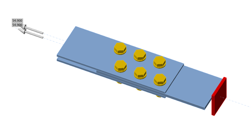
Analizler, s boyutunun sıfırdan (yani şaşırtma yok) 3 inçe kadar 0,5 inç artışlarla değiştiği birleşimler için gerçekleştirilmiştir. AISC Specification'a göre dayanım, Bölüm B4.3b hükümleri kullanılarak hesaplanmıştır. Yukarıdaki şekilde kırmızı kesik çizgi olarak gösterilen zikzak hat boyunca çekme kopması sınır durumu tüm durumlar için belirleyici olmuştur. IDEA StatiCa'ya göre dayanım, uygulanan yük girdisi programın güvenli kabul ettiği ancak küçük bir miktar (0,1 kip) artırıldığında güvensiz kabul edeceği bir değere ayarlanarak gerilme-gerinim analizi ile iteratif olarak belirlenmiştir. %5 plastik gerinim sınırı tüm durumlar için belirleyici olmuştur. Analizlerin sonuçları aşağıdaki şekilde gösterilmektedir.
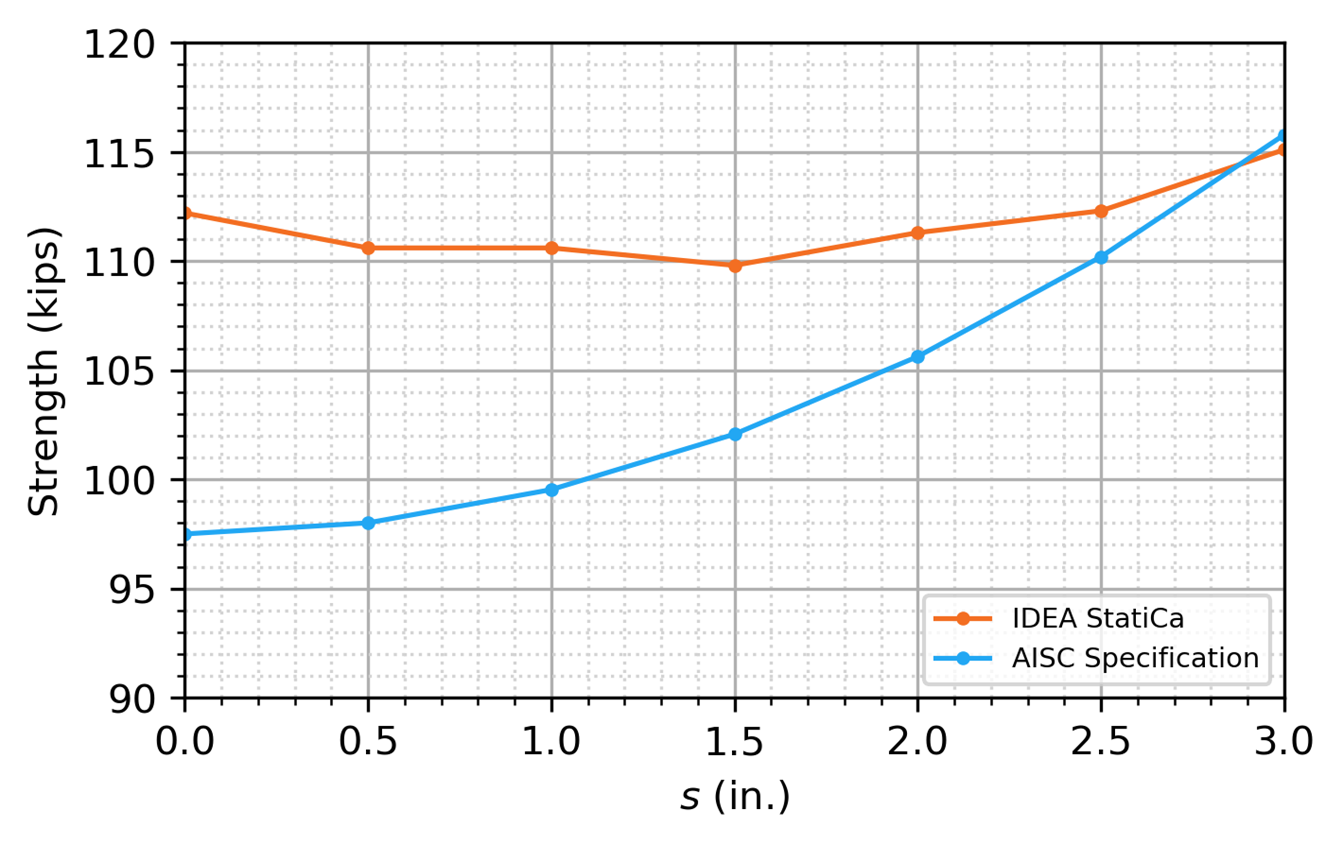
AISC Specification sonuçları, s boyutuyla birlikte dayanımın arttığına dair belirgin bir eğilim göstermektedir. IDEA StatiCa sonuçları s boyutuna daha az duyarlılık göstermekte olup s = 3 inç durumu dışında tüm durumlarda dayanım AISC Specification'dan elde edilenden daha yüksektir. Bununla birlikte, beklenen zikzak göçme örüntüsü, aşağıdaki şekilde izin verilen maksimum uygulanan yük altında test plakasındaki plastik gerinimi gösteren model tarafından yakalanmaktadır.

Köşe Kaynağı Boyutu Gereksinimleri
AISC Specification (2022) Bölüm J2.2b, köşe kaynakları için sınırlamalar içermektedir.
Bölüm J2.2b'nin (a)-(c) maddeleri, köşe kaynaklarının boyutu ve minimum uzunluğuna ilişkin geometrik sınırlamaları belirtmektedir. Bu sınırlamalar, "Kod kurulumu" bölümünde "Detaylandırma" seçeneği işaretlendiğinde hesaplama sırasında kontrol edilir. Kontrol edilen spesifik sınırlamalar bu makalede açıklanmaktadır. Herhangi bir sınırlama karşılanmazsa, kaynak detaylandırma hatası nedeniyle yönetmelik kontrolünü geçemez. Sınıra yakın veya sınırda olan boyutlar, sayısal hassasiyet veya yuvarlama nedeniyle beklendiği gibi değerlendirilemeyebilir.
Bölüm J2.2b'nin (d) maddesi, uzun uç yüklü köşe kaynakları için azaltmalar dahil olmak üzere köşe kaynaklarının etkin uzunluğunu belirtmektedir. IDEA StatiCa, köşe kaynakları için etkin uzunluğu hesaplamaz ve dolayısıyla bu hükmün yönlendirmesini kullanmaz; ancak uç yüklü köşe kaynaklarının dayanımı üzerindeki düzgün olmayan gerilme dağılımının etkisi, kaynağın ve bağlı malzemenin rijitliğinin açık modellemesi yoluyla yakalanır. Bu hükmün ayrıntılı incelemesi için bu makaleye bakınız.
Bölüm J2.2b'nin (e)-(i) maddeleri, IDEA StatiCa tarafından kontrol edilmeyen ve uygulanabilirse mühendis tarafından ayrıca değerlendirilmesi gereken sınırlamaları belirtmektedir.
Tasarım Duvar Kalınlığı HSS için
AISC Şartnamesi (2022) Bölüm B4.2, içi boş yapısal kesitler (HSS) için dayanım hesaplamalarında duvar kalınlığının tasarım duvar kalınlığı t olarak alınmasını gerektirmektedir. Tasarım duvar kalınlığı, kutu kesitler ve ASTM A1065/A1065M veya ASTM A1085/A1085M'e göre üretilen HSS için nominal kalınlık tnom'a eşittir. Tasarım duvar kalınlığı, ASTM A500/A500M dahil olmak üzere Şartname tarafından kullanım için onaylanan diğer standartlar için nominal duvar kalınlığının 0,93 katına eşittir (yani t = 0.93tnom). ASTM A500 Gr. C, Amerika Birleşik Devletleri'nde dikdörtgen ve yuvarlak HSS için tercih edilen malzeme şartnamesidir (Tavarez 2022).
IDEA StatiCa, HSS kesitlerinin duvar kalınlığını malzemeye göre otomatik olarak ayarlamamaktadır. Bu nedenle kullanıcının bu gereksinimi göz önünde bulundurması ve uygun kalınlığın atandığından emin olması gerekmektedir.
IDEA StatiCa'da kesit tanımlanırken, "HSS (AISC 15.0 - A1085, A1065)" kategorisindeki önceden tanımlanmış kesitlerde duvar kalınlığı nominal duvar kalınlığına eşitken, "HSS (AISC 15.0 - A500, A501, A618, A847)" kategorisindekiler için duvar kalınlığı nominal duvar kalınlığının 0,93 katına eşittir.
References
AISC (2022), Specification for Structural Steel Buildings, American Institute of Steel Construction, Chicago, IL.
AISC (2023), Steel Construction Manual, 16th Edition, American Institute of Steel Construction, Chicago, IL.
Dowswell, B. (2011). “A Yield Line Component Method for Bolted Flange Connections.” Engineering Journal, AISC, 48(2nd Quarter), 93–116.
Dowswell, B. (2015). “Plastic Strength of Connection Elements.” AISC Engineering Journal, 52(1st Quarter), 47–66.
Eatherton, M. R., and Murray, T. M. (2023). End-Plate Moment Connections. Design Guide 39, American Institute of Steel Construction, Chicago, Illinois.
Kulak, G. L., Fisher, J. W., and Struik, J. H. A. (1987). Guide to Design Criteria for Bolted and Riveted Joints, Second Edition. John Wiley & Sons, Inc.
Miazga, G. S., and D. L. Kennedy. (1989), “Behaviour of fillet welds as a function of the angle of loading,” Canadian Journal of Civil Engineering, 16 (4): 583–599.
Muir, L. (2015), “Bear It and Grin” Modern Steel Construction, AISC. (December).
Mohr, B. A., and Murray, T. M. (2008). “Bending Strength of Steel Bracket and Splice Plates.” Engineering Journal, AISC, 45(2), 97–106.
Tavarez, J. (2022), “Are You Properly Specifying Materials?” Modern Steel Construction, AISC. (June), 16-22.