

Introduction
Our database of connections is always growing, but we have started here with the AISC standard connections commonly used across steel connection design projects.
How to Use Workset Files
Quick how to video of how to download and open these files in IDEA StatiCa.
Beam - Column Flange Joints
Carousel of Beam-Column Flange
Weld Rupture
The AISC Specification includes provisions for groove welds, fillet welds, and plug and slot welds. Of these, complete joint penetration (CJP) groove welds and fillet welds are the only types that can currently be defined in IDEA StatiCa.
CJP groove welds and butt welds in IDEA StatiCa, are modeled by directly connecting the components using multi-point constraints. The multi-point constraints introduce no flexibility. Also, the strength of these welds is not checked since the strength of the CJP groove welds is controlled by the base metal.
Fillet welds are also modeled using multi-point constraints and an equivalent weld shell element that approximates the elastoplastic behavior of the weld. The forces in these shell elements are extracted and used as required strengths for comparison to available strengths computed according to the AISC Specification.
The available strength of welds is defined in AISC Specification Section J2.4. For fillet welds, the nominal strength is the product of the nominal stress of the weld metal, Fnw, the effective area of the weld, Awe, and a directional strength increase factor, kds. AISC Specification Table J2.5 sets Fnw = 0.6FEXX and references AISC Specification Section J2.2a for the definition of Awe. For each weld segment, Awe is taken as the throat thickness times the length of the weld segment. The reductions to the effective length for long welds in AISC Specification Section J2.2b are not applied; however, the effects of long welds are captured explicitly as described in the entry on Deformation Compatibility in Long Connections.
The directional strength increase factor is defined in AISC Specification Section J2.4. When strain compatibility of the various weld elements is considered (as is the case in IDEA StatiCa because the stiffness of the welds and connecting elements are explicitly modeled), kds is a function of the angle between the line of action of the required force and the weld longitudinal axis. IDEA StatiCa determines the line of action from the internal forces in the equivalent weld shell element and computes kds and the nominal strength for each weld segment.
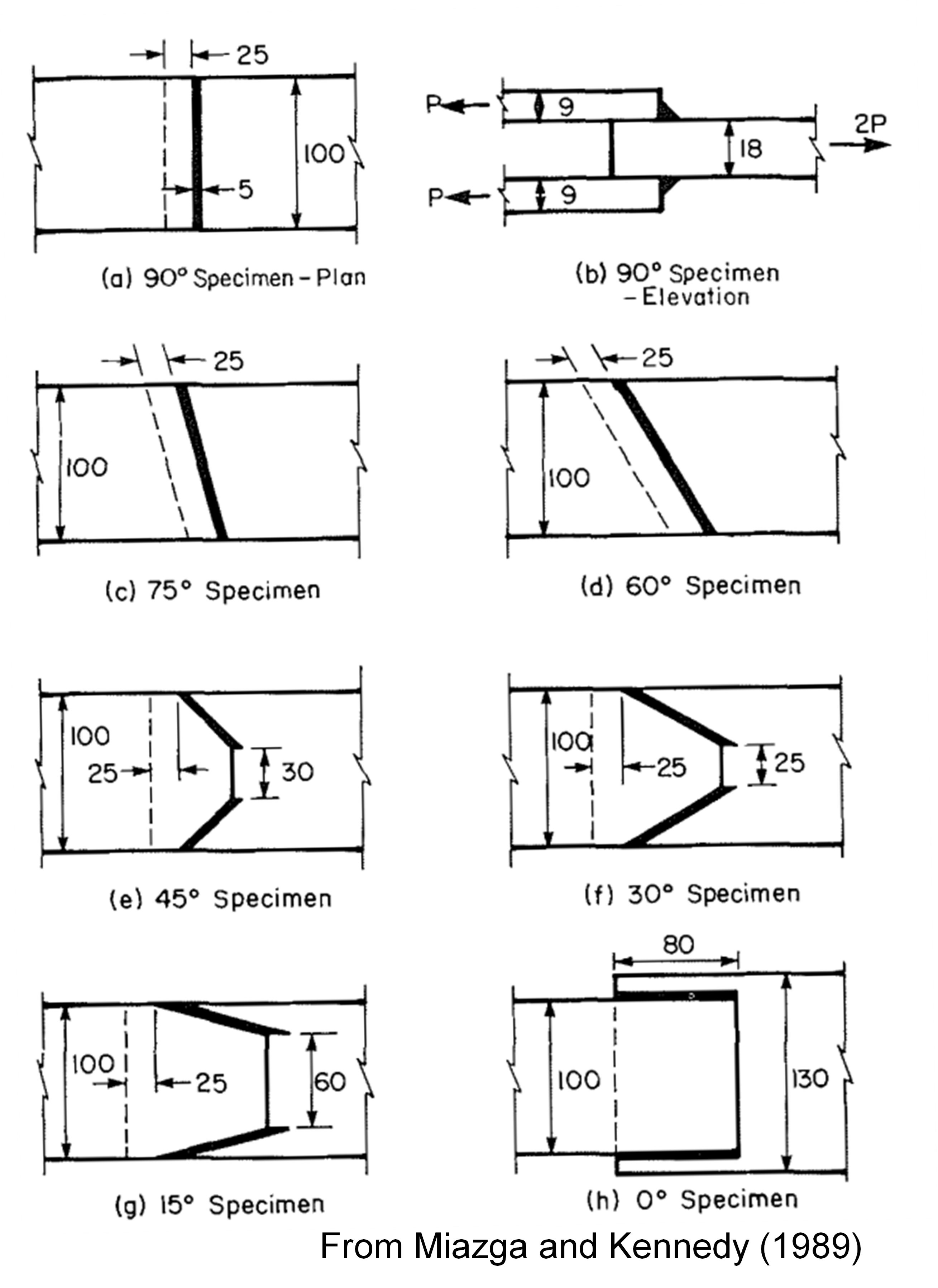
To illustrate the effect of the directional strength increase, consider the welded specimens tested experimentally by Miazga and Kennedy (1989). The specimens had loading angles of 0, 15, 30, 45, 60, 75, and 90 degrees as shown in the figure below where the units are millimeters. The plates were fabricated with CAN3-G40.21-M8 grade 300W steel. The exterior plates had a measured yield strength of 52.8 ksi. The interior plates had a measured yield strength of 50.2 ksi. E48014 electrodes with a nominal strength of FEXX = 70 ksi were used.

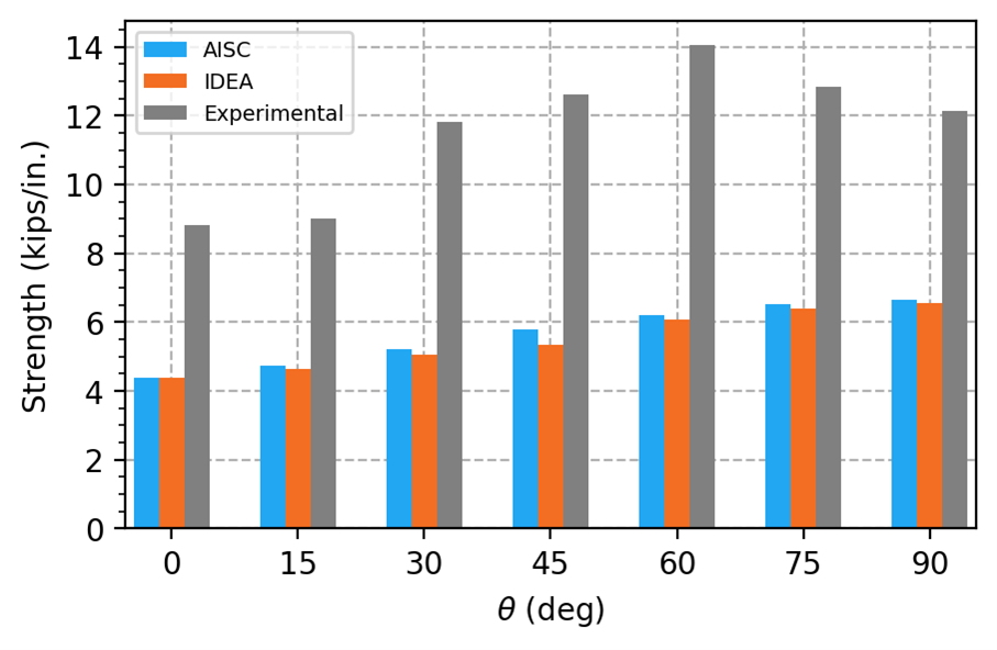
The maximum permitted applied loads were determined for each specimen in IDEA StatiCa using models with measured plate material properties, nominal filler metal properties, and including resistance factors. The maximum permitted applied loads were normalized by the total length of weld in the connection and are shown in the figure below. Also shown are the design strength according to the AISC Specification (including the directional strength increase factor and resistance factor) and the experimental strength.
The angle of loading measured from the weld longitudinal axis for each specimen, as output by IDEA StatiCa in the weld results, is listed in the table below.
| Geometric \(\theta\) (deg) | IDEA \(\theta\) (deg) |
| 0 | 14.7 |
| 15 | 21.1 |
| 30 | 34.0 |
| 45 | 49.1 |
| 60 | 58.8 |
| 75 | 72.6 |
| 90 | 89.9 |
The IDEA StatiCa and AISC Specification strengths are both much less than the experimental strengths. There are several reasons the experimental strengths are higher: they do not include resistance factors, the actual filler metal strength is likely more than the nominal strength, and the actual failure area of the weld is likely greater than assumed in design calculations.
The strengths from IDEA StatiCa are slightly less than those according to the AISC Specification, but both show an increase with loading angle. Furthermore, the geometric angle of the specimen differs from the angle of loading measured from the weld longitudinal axis as output by IDEA StatiCa. These differences occur because welds are divided into short segments when modeled in IDEA StatiCa. Unlike traditional calculations where the demands along the length of the weld are assumed to be uniform, the weld segments experience different demands based on the stiffness of the weld and connecting elements. The angle output by IDEA StatiCa is for the weld segment that has the greatest utilization ratio. Often this is a segment at the end of a weld. For these specimens, the aggregate effect of the non-uniform demands is a slight reduction in strength.
A special case applies for fillet welds to the ends of rectangular HSS loaded in tension where kds = 1.0. In IDEA StatiCa, the directional strength increase factor is not used for fillet welds to the ends of rectangular HSS, regardless of loading.
AISC Specification Section J2.4 also defines the strength of the base metal. For fillet welds, AISC Specification Table J2.5 references AISC Specification Section J4 for base metal checks. Base metal strength checks are described in greater detail in the entry on Weld Base Metal Strength.
Weld Base Metal Strength
In welded connections, the strength of the connecting elements adjacent to the weld is called base metal strength. In many cases, potential limit states can be identified, and the available strength of the base metal can be computed using the provisions of AISC Specification Section J4. The evaluation of these limit states in IDEA StatiCa is described in entries on the individual limit states, including Tensile Yielding, Tensile Rupture, Shear Yielding and Rupture, and Block Shear Rupture.
However, in some connections, potential limit states adjacent to the weld are hard to identify, and the available strength of the base metal cannot be directly computed by hand. For these cases, the AISC Manual provides Equations 9-6 and 9-7 for the minimum base metal thickness that matches the weld with some assumptions. This equation is not evaluated in IDEA StatiCa since potential base metal limit states need not be identified a prior, and strength is assessed with the 5% plastic strain limit. However, engineers may still use the limit to size welds and connecting elements.
IDEA StatiCa provides an option to check base metal capacity at the fusion face. This check can be enabled in the “Code setup” window. This check is not commonly performed in US practice and is generally not necessary when the filler metal is appropriately matched to the base metal. The commentary on AISC Specification Section J2.4 states that tests have demonstrated that the stress on the fusion area is not critical in determining the shear strength of fillet welds.
Bolt Shear and Tensile Rupture
The available strength of bolts subject to tension or shear is defined in AISC Specification Section J3.7. The available strength of bolts subject to combined tension and shear is defined in AISC Specification Section J3.8. IDEA StatiCa uses these provisions directly to compute available strengths, compared to required strengths determined from nonlinear analysis. As specified, the required tensile strength determined from nonlinear analysis includes tension resulting from prying action.
A footnote in AISC Specification Table J3.2 requires that the nominal shear stress, Fnv, of A307 bolts be reduced when the grip of a bolt is greater than five times its diameter. This reduction is not implemented in IDEA StatiCa. Therefore, the nominal shear stress of long A307 bolts needs to be manually adjusted in the materials tab.
Bearing and Tearout at Bolt Holes
The strength of bolts in shear can be limited by bearing or tearout at the bolt holes. It is sometimes common practice to evaluate bearing and tearout separate from bolt shear rupture. However, bolt groups can fail with some bolts rupturing and others tearing out. A user note in AISC Specification Section J3.7 states “The effective strength of an individual fastener may be taken as the lesser of the fastener shear strength per Section J3.7 or the bearing or tearout strength at the bolt hole per Section J3.11. The strength of the bolt group is taken as the sum of the effective strengths of the individual fasteners.”
IDEA StatiCa evaluates the strength of each bolt individually, with required strengths determined from the nonlinear analysis and available strengths calculated using the provisions of the AISC Specification. This evaluation complies with the user note in AISC Specification Section J3.7. However, IDEA StatiCa does not simply sum up the effective strengths of the individual fasteners. The approach taken by IDEA StatiCa can result in a conservative underestimation of strength.
Consider the three-bolt connection shown below. The connection is short and the stiffness of the three bolts is equal because the load-deformation response for bolts in IDEA StatiCa does not depend on edge distance, therefore the applied load is shared approximately equally among the bolts. The strength of the bolt with the 1 in. edge distance is controlled by tearout. IDEA StatiCa indicates failure when the first bolt reaches 100% utilization. Since the bolt with 1 in. edge distance has the lowest available strength (ϕrn = ϕ1.2dtFu = 17.4 kips), it reaches 100% utilization first. The other bolts are stronger (ϕrn = 35.8 kips, AISC Manual Table 7-1) but they do not reach 100% utilization, resulting in a connection strength of 52.5 kips. By traditional calculations, each bolt is assumed to reach its effective strength, resulting in a connection strength of 89.0 kips, 70% greater than the strength from IDEA StatiCa.
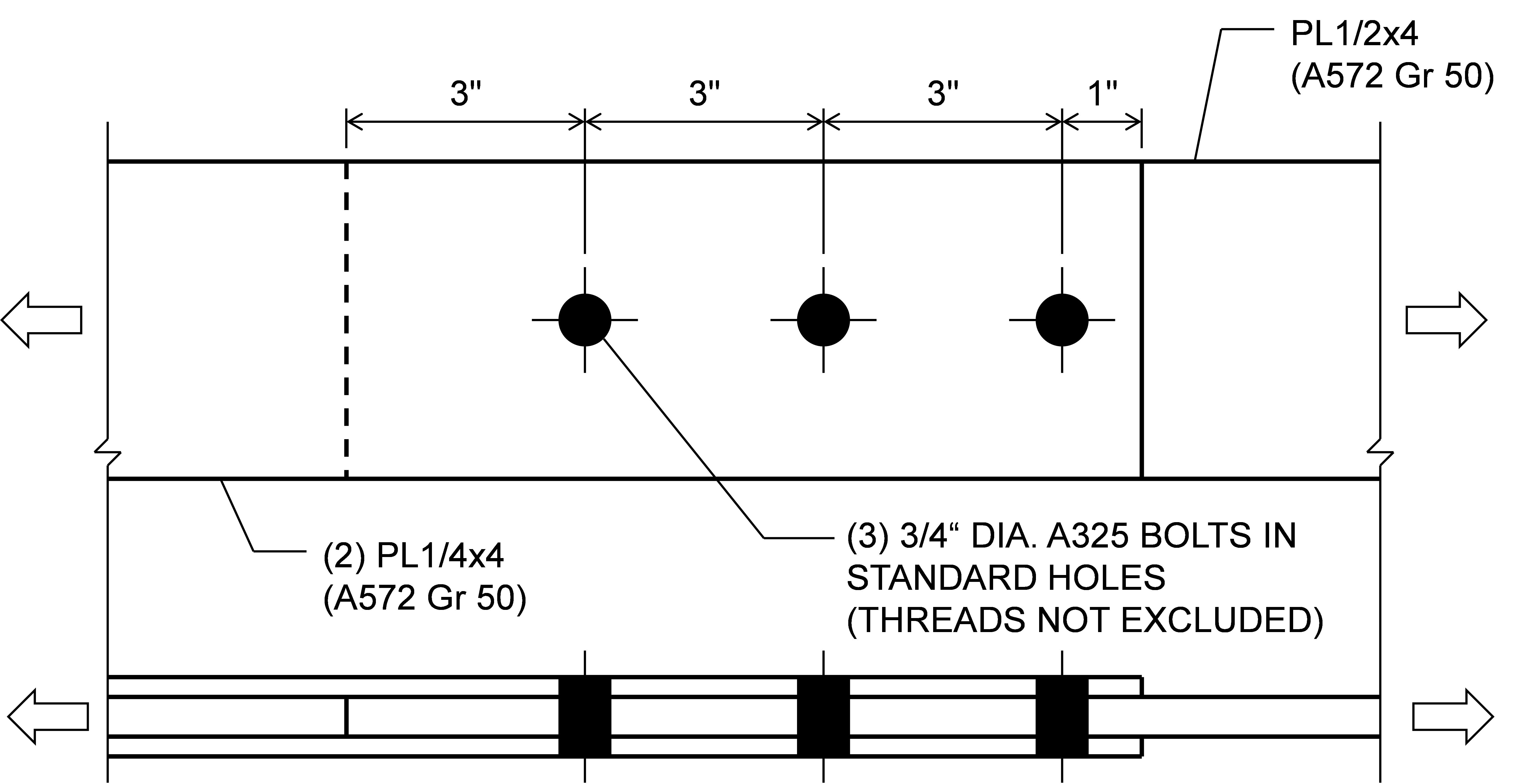
Three-bolt bolted connection
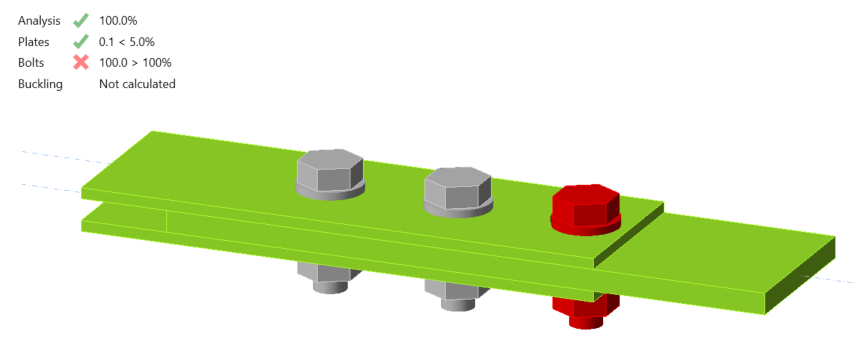
Three-bolt bolted connection with 57.5 kips of applied load
Two sets of equations are provided in AISC Specification Section J3.11a, one when deformation at the bolt hole at service load is a design consideration and one when deformation at the bolt hole at service load is not a design consideration. The choice of whether deformation at the bolt hole at service load is a design consideration can be made in the “Code setup” window.
Different equations are also provided in AISC Specification Section J3.11a for long-slotted holes when the slot is perpendicular to the direction of force. Slotted holes can be defined in IDEA StatiCa using the plate editor. The bearing and tearout equations in the AISC Specification for long-slotted holes are used for all slotted holes in IDEA StatiCa, regardless of slot length.
AISC Specification Section J3.11b requires the use of the bearing provisions of Section J7 for bolts or rods that pass completely through an unstiffened box member or hollow structural section (HSS). This provision is not implemented in IDEA StatiCa and bearing is evaluated in such connections as though they are regular bolted connections with all plies making firm contact. A warning is provided in the report if the bolt grip length is larger than the sum of the thicknesses of connected plates.
When evaluating tearout, IDEA StatiCa determines the clear distance, in the direction of the force, between the edge of the hole and the edge of the adjacent hole or edge of the material, lc, using the direction of force for each bolt from the nonlinear analysis. This feature is particularly helpful for eccentrically loaded bolt groups where the direction of force varies from bolt to bolt. The tearout limit state was investigated for bracket plate connections in this article and for single plate shear connections in this article.
Bearing (Local Compressive Yielding)
AISC Specification Section J7 defines the available strength for the limit state of bearing (local compressive yielding). These provisions apply to specific cases of contact between steel components but are not implemented in IDEA StatiCa.
For finished surfaces and ends of fitted bearing stiffeners, while the contact bearing pressure is not checked against the limit prescribed in the AISC Specification, stresses in contacts can be plotted and yielding of the steel components often provides a more controlling limit since the allowable bearing pressure exceeds the yield strength.
IDEA StatiCa evaluates the bearing strength of bolts or rods that pass completely through an unstiffened box or HSS member as though they are regular bolted connections with all plies making firm contact and not using the provisions of AISC Specification Section J7. A warning is provided in the report if the bolt grip length is larger than the sum of the thicknesses of connected plates. See also Bearing and Tearout at Bolt Holes.
Expansion rollers and rockers cannot be modeled in IDEA StatiCa. Pins were introduced to IDEA StatiCa in version 24.0 and are currently only available for design by Eurocode.
Slip
Connections are required to be designed as slip-critical when they are subject to fatigue load with reversal of loading direction, when they use oversized holes, when slip at the faying surfaces would be detrimental to the performance of the structure, and for other reasons. Available strength for the limit state of slip is defined in AISC Specification Section J3.9 with additional provisions in Section J3.10 for combined tension and shear in slip-critical connections. IDEA StatiCa uses these provisions directly to compute available strengths which are compared to required strengths determined from nonlinear analysis.
The slip coefficient, μ, is defined in the code setup. The factor for fillers, hf, is determined automatically.
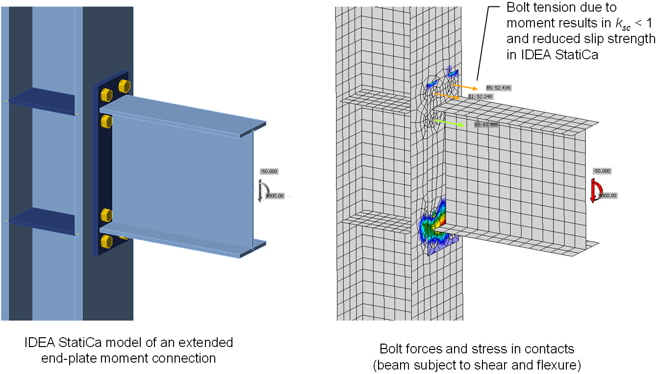
Differences between IDEA StatiCa and hand calculations can occur because of the reduction factor for tension, ksc, defined in AISC Specification Section J3.10. IDEA StatiCa uses the tension in the bolt from the nonlinear analysis to calculate ksc, even if the tension in the bolt was not caused by applied tension that reduces the net clamping force. For example, in an extended end-plate moment connection with a slip-critical connection between the end plate and the column flange (such as shown below), moment in the beam causes tension in the bolts in IDEA StatiCa. Physically, any loss of clamping force near the bolts on the tension side of the beam due to moment will be offset by an increase in clamping force near the bolts on the compression side of the beam. In hand calculations, the factor ksc would not be used for this connection (unless the beam has a net tension force). But since IDEA StatiCa evaluates bolts individually, ksc is conservatively applied to the bolts on the tension side of the beam reducing the overall slip strength of the connection. Incidental tension in a predominantly shear-loaded connection and tension from prying action are also conservatively included when calculating ksc in IDEA StatiCa.
AISC Specification Section J3.9 requires that slip-critical connections be designed for the limit states of bearing-type connections in addition to slip. IDEA StatiCa does not check bolt rupture, bearing, or tearout for bolts designated to transfer force through friction. Additionally, slip-critical connections are modeled differently than bearing-type connections in IDEA StatiCa. In slip-critical connections, the forces are transferred from one plate to another over a larger area more representative of force transfer through friction. The larger spread of transfer forces can lead to increased strength of connecting elements for limit states such as block shear rupture. For most connections, slip strength is less than the strength for the limit states of bearing-type connections. However, engineers should be aware of these limitations and address them in design. It is recommended that slip-critical connections be analyzed twice in IDEA StatiCa: once as a slip-critical connection (i.e., with shear force transfer type set to “Friction”) and again as a bearing type connection (i.e., with shear force transfer type set to “Bearing – tension/shear interaction”) to ensure all limit states are evaluated appropriately.
Tensile Yielding
Tensile yielding is among the most fundamental limit states in structural steel design. The nominal strength for tensile yield is defined in AISC Specification (2022) Section D2 for tension members and Section J4.1 for connecting elements as the specified minimum yield stress, Fy, times the gross area, Ag. Despite the simplicity of this equation, it is not used to assess strength in IDEA StatiCa. Members and connecting elements are modeled in IDEA StatiCa with shell elements that are assigned a nonlinear stress-strain relationship consisting of a linear elastic region and a linear plastic region. Shell elements can experience stress along multiple axes and the stress-strain relationships account for this. If subject to uniaxial stress, the stiffness in the elastic range is the modulus of elasticity, E, the stiffness in the plastic range is one-thousandth of the modulus of elasticity, E/1000, and the transition between elastic and plastic occurs at a stress of Fy times a resistance factor of 0.9 for LRFD or divided by a safety factor of 1.67 for ASD.
Instead of limiting the required strength to be no more than the available strength (e.g., Ru ≤ ϕRn), IDEA StatiCa limits plastic strain to 5%. While this is a fundamentally different assessment, resulting strengths for tensile yield of the gross section of a member or component from the two approaches will never differ by a large amount. Minor differences can arise for two reasons: 1) the small increase in stress after yielding in IDEA StatiCa and 2) small differences in cross-sectional area.
A small post-yield stiffness (one-thousandth of the elastic stiffness) is used in IDEA StatiCa to avoid the computational difficulties that would arise with zero post-yield stiffness. At the 5% plastic strain limit, this results in approximately 0.05×E/1000 = 0.05×(29,000 ksi)/1000 = 1.45 ksi stress above the yielding stress. For ASTM A992 steel with a Fy of 50 ksi and using LRFD, tensile yield initiates in IDEA StatiCa at 0.9×50 ksi = 45 ksi. The extra 1.45 ksi of stress accumulated post-yield can lead to an approximately 3% increase in strength.
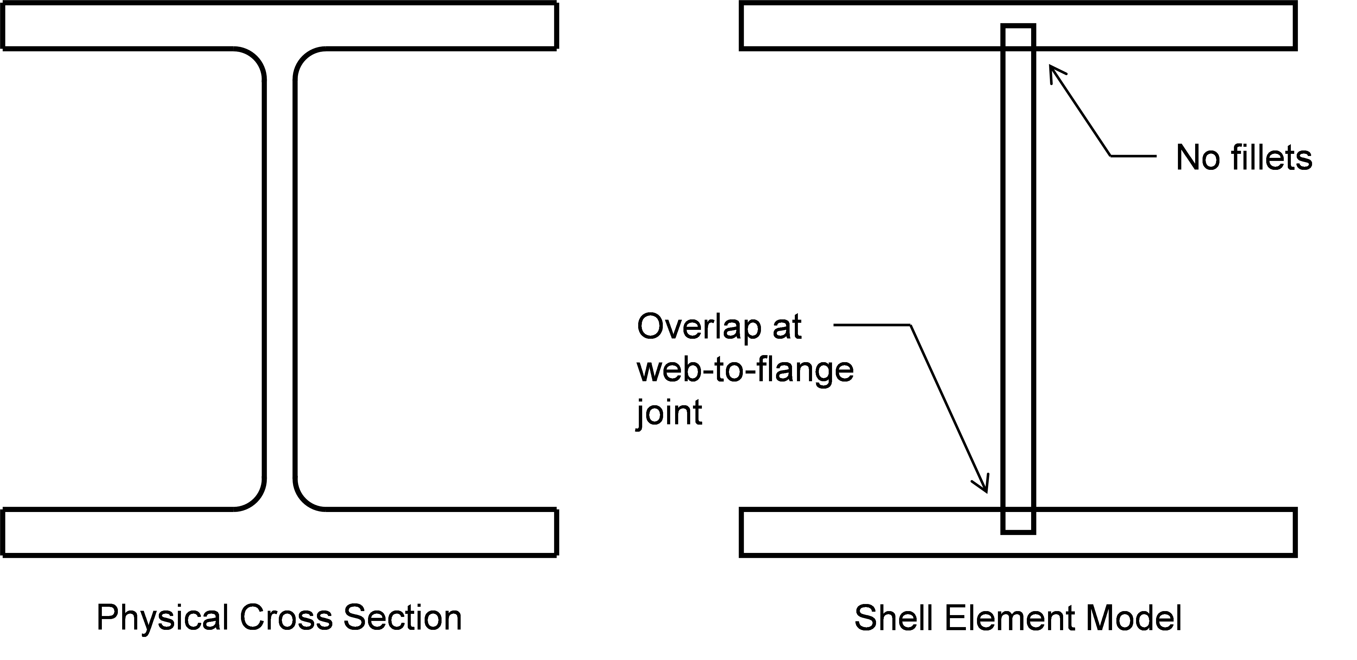
Structural steel members are modeled with shell elements in IDEA StatiCa resulting in some simplifications of the physical geometry. The shell elements only represent rectangular components thus fillets are neglected. Additionally, since shell elements are connected at nodes located at the center of thickness, there is some overlap at joints of cross-sectional elements. The figure below shows the simplifications for a wide flange shape. The simplifications cause small differences in cross-sectional area which can affect tensile yield strength. For a W14x159, the cross-sectional area listed in AISC Manual Table 1-1 is 46.7 in.2. The cross-sectional area when modeled as in IDEA StatiCa is 2bftf+(d-tf)tw = 2(15.6 in.)(1.19 in) + (15.0 in. – 1.19 in.)(0.745 in.) = 47.4 in.2, where the cross-sectional dimensions were also determined from AISC Manual Table 1-1. This is a 1.5% difference.
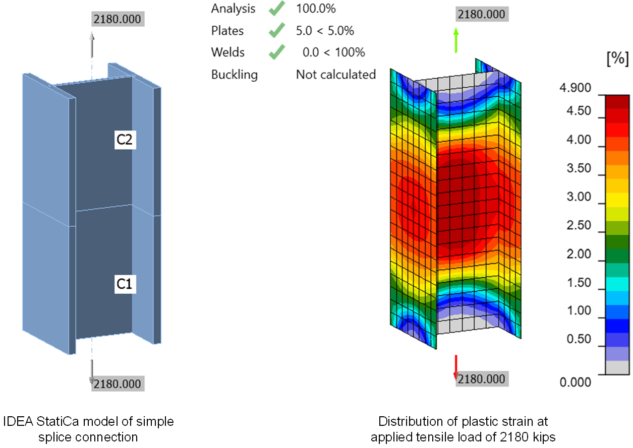
The overall effect of these minor differences can be observed in a simple IDEA StatiCa model of a splice connection between two W14x159 (ASTM A992) steel shapes. The splice is butt welded (e.g., CJP) and loaded in tension. Per the AISC Specification (2022), the design strength of the wide flange tension member is 0.9×(50 ksi)×(46.7 in.2) = 2,100 kips. The maximum load that can be applied to the connection in IDEA StatiCa (version 22.1) is 2,180 kips, 4% greater than the design strength as calculated per the AISC Specification. The distribution of plastic strain in the connection shows that the full cross-section has yielded.
Tensile Rupture
Provisions for the limit state of tensile rupture are in AISC Specification Chapter D. These provisions are referenced in AISC Specification Section J4.1 for connecting elements. The nominal strength for tensile rupture is calculated as the tensile strength of the material, Fu, times the effective net area, Ae. The effective net area accounts for material removed, including bolt holes, and the effect of shear lag through the shear lag factor, U, defined in AISC Specification Table D3.1. A resistance factor of ϕ = 0.75 is applied to the nominal strength to determine the design strength.
The limit state of tensile rupture is not directly evaluated in IDEA StatiCa. It is captured by limiting the amount of plastic strain any component can experience. The default plastic strain limit in IDEA StatiCa is 5%. Neither Fu nor the resistance factor of ϕ = 0.75 are used in IDEA StatiCa. IDEA StatiCa uses a bilinear stress-strain relationship in which yield occurs at the yield stress of the steel, Fy, times a reduction factor equal to 0.9 by default (the user can adjust this factor). After yield, the stiffness of steel is only one thousandth of the modulus of elasticity. This post yield stiffness is included for numerical stability and does not provide any significant strain hardening. Additionally, IDEA StatiCa does not use the shear lag factors of AISC Specification Table D3.1. Instead, shear lag is modeled explicitly.
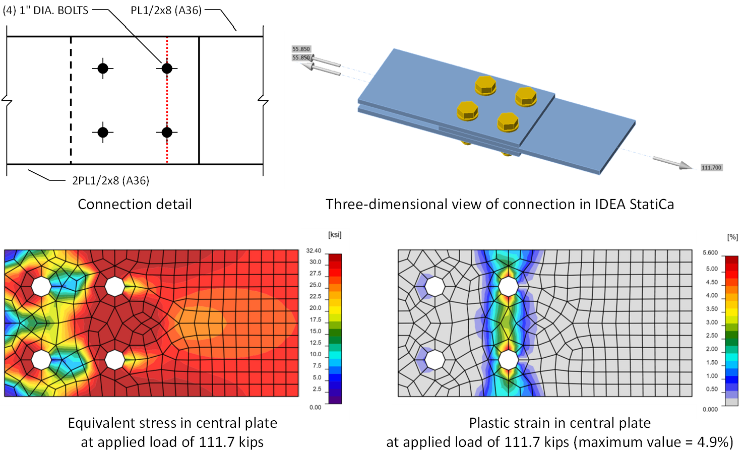
Also, the stresses that develop in connection regions are rarely purely uniaxial. IDEA StatiCa uses the von Mises yield criterion to identify when yielding occurs under these complex stress states which can lead to an apparent increase in strength. To illustrate this effect, consider the simple splice connection shown in the figure below. The strength of the central plate near the bolts controls the strength of this connection. Based on hand calculation procedures, one may expect that the strength that IDEA StatiCa will determine would be the stress at which yielding occurs times the net area (shown by a red dotted line in the figure). For this connection, the net area is (1/2 in.)×(8 in. – 2dh) = 2.875 in.2, where the diameter of the hole, dh, equals 1-1/8 in. (note that IDEA StatiCa does not include the 1/16 in. for damage described in AISC Specification Section B4.3b, see the entry on Net Area Determination for additional information - ADD ANCHOR). For LRFD, the stress at which yielding occurs in IDEA StatiCa is 0.9Fy and there is minimal strain hardening (see the entry on Tensile Yielding for additional information). For the A36 material used in this example, yielding will occur at 0.9(36 ksi) = 32.4 ksi. Therefore, one may expect that the strength of this connection in IDEA StatiCa would be (2.875 in.2)×(32.4 ksi) = 93.1 kips. However, because the stress is not purely uniaxial at the net section, the other components of stress effectively increase the yield stress normal to the net area, and 5% plastic strain is not achieved until an applied load of 111.7 kips.
Taken individually, the differences between traditional calculations and IDEA StatiCa result in lower strengths in IDEA StatiCa (only using Fy and not Fu), higher strengths in IDEA StatiCa (using a material strength reduction factor of 0.9 instead of ϕ = 0.75), and different strengths depending on the specific connection (explicitly modeling shear lag instead of using the shear lag factor, U). Taken together, the differences usually, but not always, result in equal or lower strength from IDEA StatiCa than from traditional calculations.
The limit state of tensile rupture was investigated in this study through comparison to hundreds of experimental results. The results show that IDEA StatiCa is generally conservative, especially at the nominal strength level, but there are some cases where the available strength from IDEA StatiCa is greater than that calculated according to the AISC Specification. Using measured material and geometric properties without resistance factors applied, the strength from IDEA StatiCa was less than or equal to the experimentally observed strength for all but 12 specimens out of 529 (9 of which were fabricated with high-strength steel, Fy = 122.8 ksi) and less than or equal to the expected tensile rupture strength computed using design equations for all but 30 specimens out of 529. Using nominal material and geometric properties with resistance factors applied, the strength from IDEA StatiCa was found to be greater than the strength computed according to the AISC Specification for some connections without physical counterparts, especially plate tension members with relatively short welds, and rectangular HSS tension members. Given that the experimental data for these cases is limited, work is ongoing to determine if the differences are the result of unconservatism in IDEA StatiCa or conservatism in the AISC Specification equations.
Compressive Yielding and Buckling
The available strength of affected elements of members and connecting elements in compression is defined in AISC Specification Section J4.4. When the slenderness ratio, Lc/r, is less than or equal to 25 compressive yielding applies and the nominal strength is computed as the product of the specified minimum yield stress and the gross area (i.e., Pn = FyAg). Like for Tensile Yielding, the limit state of compressive yielding is evaluated in IDEA StatiCa with the 5% plastic strain limit.
When the slenderness ratio, Lc/r, is greater than 25, the provisions of AISC Specification Chapter E apply. Limit states in AISC Specification Chapter E include flexural buckling, torsional buckling, and flexural-torsional buckling. The nonlinear analysis performed in IDEA StatiCa is nonlinear because it includes effects such as yielding and contact. The analysis typically does not consider geometric nonlinearities such as P-Δ effects (geometric nonlinearities are considered when HSS are used as bearing members).
Engineers must also perform a linear buckling analysis to detect buckling. A linear buckling analysis can determine the elastic buckling load, expressed as a ratio of the applied load. While providing useful information that can guide design, the linear buckling analysis does not consider potential yielding that can reduce stiffness and the buckling load (i.e., inelastic buckling), nor does it consider the effects of initial geometric imperfections. Because of these limitations, to use IDEA StatiCa, the connection needs to be stocky enough that neither elastic buckling nor inelastic buckling will occur. The elastic buckling load ratio provides a convenient measure of stockiness (or slenderness).
Consider the slenderness ratio limit in AISC Specification Section J4.4 of Lc/r ≤ 25 to assume compressive yielding. A slenderness ratio of Lc/r = 25 corresponds to an elastic critical stress Fe = π2E/(Lc/r)2 = π2(29,000 ksi)/(25)2 = 458 ksi. For A36 steel, this corresponds to 14 times the factored yield stress for LRFD and 21 times the factored yield stress for ASD. For grade 50 steel, the elastic critical stress corresponds to 10 times the factored yield stress for LRFD and 15 times the factored yield stress for ASD. Accordingly, the elastic buckling load ratio should be kept greater than these ratios to avoid cases where inelastic buckling could control.
The appropriate limit on the elastic buckling load ratio varies based on the connection configuration. For plate buckling, the limit is much lower. Based on the limiting width-to-thickness limits in AISC Specification Table B4.1a, the elastic critical buckling load ratio should be kept to no less than 3 for LRFD and 4.5 for ASD . An evaluation of bracket plates identified elastic critical buckling load ratio limits of 4 for LRFD and 6 for ASD. The use of a critical buckling load ratio limit of 3 has been evaluated for bearing stiffeners (report coming soon), coped beams, and beam-over-column connections.
Elements of connections that are slender enough for inelastic buckling to occur still have strength, potentially enough strength for a given application. However, without the capability to accurately quantify inelastic buckling strength in IDEA StatiCa these cases must be avoided.
Shear Yielding and Rupture
The available strength of affected elements of members and connecting elements in shear is defined in AISC Specification Section J4.2. This section describes two limit states: shear yielding and shear rupture. For both limit states, IDEA StatiCa does not compute the available strength per the AISC Specification, but rather relies on the 5% plastic strain limit to evaluate if the connection is sufficiently strong.
In tension, the stress-strain relationship used in IDEA StatiCa is linear up to yield, with a stiffness equal to the modulus of elasticity, then linear thereafter, with a stiffness equal to one-thousandth of the modulus of elasticity. Yield in tension occurs at the specified minimum yield stress of the steel, Fy, times 0.9 for LRFD or divided by 1.67 for ASD. IDEA StatiCa uses the von Mises yield criterion to determine when yielding begins under multi-axial states of stress. According to the von Mises yield criterion, material subject to pure shear will yield when the shear stress equals the yield stress divided by the square root of 3. The inverse of the square root of 3 is approximately equal to 0.577 which is approximately equal to the 0.6 factor applied to the shear strength equations in the AISC Specification. This difference, or similar differences when the element is not strictly in pure shear, can lead to differences between IDEA StatiCa and traditional calculations. The small amount of strain hardening can also lead to differences as described in the entry on Tensile Yielding.
Differences can also arise because in AISC Specification Section J4.2, the resistance factor for shear yielding is defined as 1.00 and the safety factor for shear yielding is defined as 1.50. IDEA StatiCa does not utilize these factors and instead reduces the yield point by a factor of 0.9 for LRFD or by dividing by 1.67 for ASD based on the typical resistance factor and safety factor for yielding.
Other differences exist for the limit state of shear rupture. As described for the limit state of Tensile Rupture, IDEA StatiCa does not utilize the tensile strength of the steel, Fu, nor the resistance factor or safety factor for shear rupture. Again, the yield point in tension is taken as 0.9Fy for LRFD and Fy/1.67 for ASD. The result of these differences depends on the ratio of the material strengths. Also in bolted connections, the net area subjected to shear typically passes through the centerlines of the bolts. The distribution of plastic strains at the limit point in IDEA StatiCa can be different, as was seen for single plate shear connections in this article.
As an example of the combined result of the differences between the AISC Specification equations and IDEA StatiCa, consider the two beam splice connections shown in the figures below. For both, two W27×94 beams made of A992 steel are connected by splice plates on either side of the web. The splice plates are 3/8 in. thick and made of A36 steel.
The welded connection is controlled by shear yielding of the splice plates. The design strength for the plates is ϕRn = ϕ0.6FyAgv = (1.0)0.6(36 ksi)(2 × 3/8 in. × 16 in.) = 259 kips. In IDEA StatiCa, the splice plates reach a plastic strain of 5% when subject to a shear load of 236 kips. The difference in strengths is mostly due to the use of ϕ = 1.0 in the AISC Specification equations and a reduction of 0.9 on the yield stress in IDEA StatiCa.
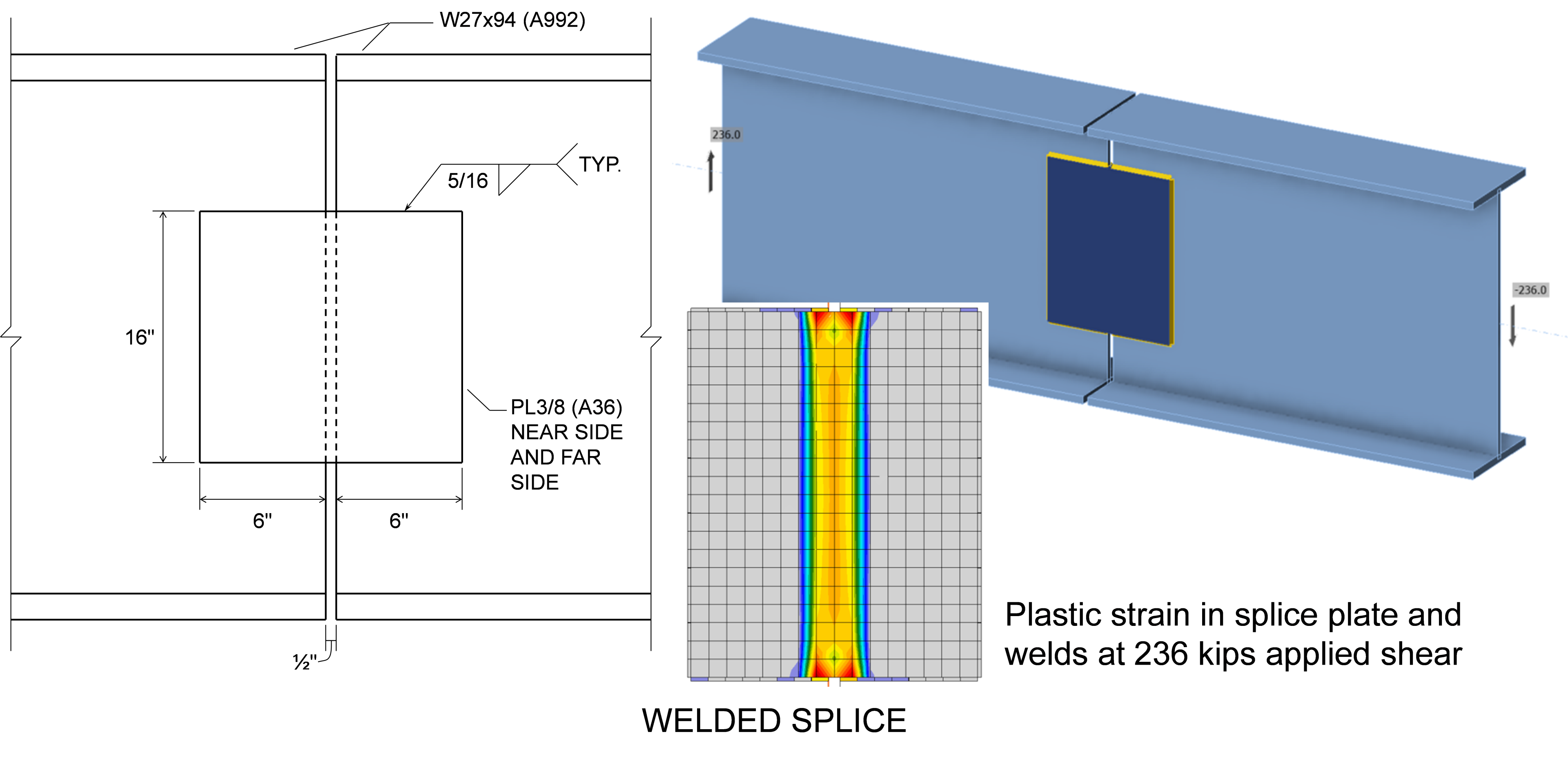
The bolted connection is controlled by shear rupture of the splice plates. The design strength for the plates is ϕRn = 210 kips. In IDEA StatiCa, the splice plates reach a plastic strain of 5% when subject to a shear load of 213 kips, nearly the same as the design strength according to the AISC Specification, indicating that the differences counteract each other and result in a safe design.

Yielding Under Combined Actions
Members and connecting elements are often subject to multiple actions simultaneously, including axial force, bending moment, shear, and torsion. AISC Specification Section J4 does not provide specific requirements for connecting elements subject to combined actions. However, AISC Manual Part 9 describes several approaches for assessing connecting elements subject to combined actions. One approach is to superimpose stresses calculated based on elastic beam theory and use a first yield criterion. Another approach is to use interaction equations that approximate the limit of plastic strength. One such equation that applies to rectangular members under in-plane loading is AISC Manual Equation 9-1.
\[ \frac{M_r}{M_c} + \left ( \frac{P_r}{P_c} \right )^2 + \left ( \frac{V_r}{V_c} \right )^4 \le 1.0 \]
where Mr, Pr, and Vr are the required flexural, axial, and shear strengths, respectively; and Mc, Pc, and Vc are the available flexural, axial, and shear strengths, respectively.
Dowswell (2015) presented a more general equation for rectangular members under in-plane and out-of-plate loading.
\[ \left ( \frac{P_r}{P_c} \right )^2 + \left ( \frac{T_r}{T_c} \right )^2 + \left ( \frac{V_r}{V_c} \right )^4 + \left ( \left ( \frac{M_{rx}}{M_{cx}} \right )^{1.7} + \left ( \frac{M_{ry}}{M_{cy}} \right )^{1.7} \right )^{0.59} \le 1.0 \]
where Tr, Mrx, and Mry are the required torsional, major-axis flexural, and minor-axis flexural strengths, respectively; and Tc, Mcx, and Mcy are available torsional, major-axis flexural, and minor-axis flexural strengths, respectively.
In IDEA StatiCa, connecting elements are modeled with shell finite elements that are assigned a multi-axial plasticity material model that uses the von Mises yield criterion (use of the von Mises yield criterion is also described in AISC Manual Part 9). As load is applied in the model, the individual shell elements experience general states of stress which are evaluated using the criterion to determine if yielding has occurred. If yielding occurs, the stiffness of the material is reduced to 1/1000 of the initial stiffness and the analysis continues.
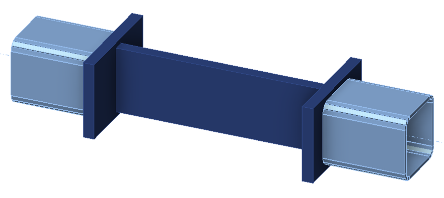
To illustrate the differences between strengths computed using interaction equations and IDEA StatiCa, consider the connection shown below. The middle “test” plate has a thickness of 1 in., height of 6 in., a length of 10 in., and is made of A36 steel. Both the connecting plates and hollow section members were selected to be strong and stiff. Analyses were performed subjecting the test plate to biaxial loading, consisting of axial tension and bending moment about the major- and minor-axes to determine maximum permitted applied loads (i.e., the loads which cause 5% plastic strain in the test plate). For these analyses, the geometric nonlinear (GMNA) option was turned off in the code setup. Also, the maximal size of elements was changed to 0.25 in. and the minimal size of elements was changed to 0.10 in. to create a finer mesh and capture the stress distribution more accurately.
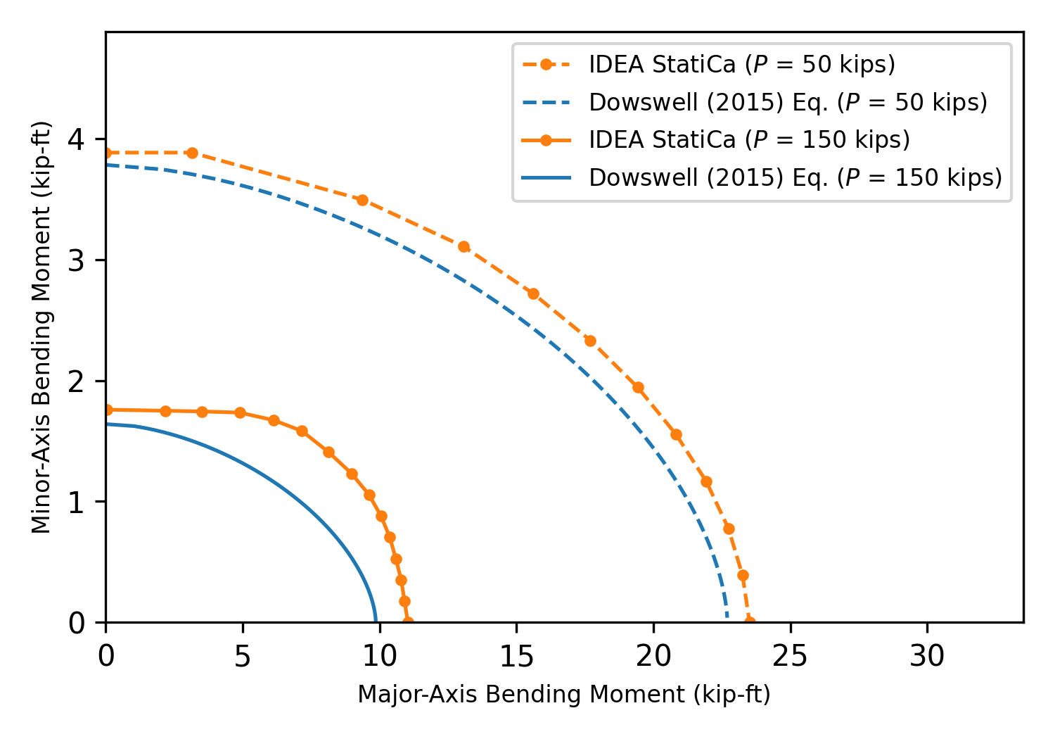
Results of the IDEA StatiCa analyses are shown in the figure below. Interaction diagrams based on the Dowswell (2015) equation are also shown in the figure. Available strengths used for the calculated interaction diagrams are Pc = ϕPn = 194.4 kips, Mcx = ϕMnx = 24.3 kip-ft, and Mcy = ϕMny = 4.05 kip-ft. Differences are seen between the IDEA StatiCa results and those from the interaction equation, including when only one action is applied. The causes of the differences under a single action are described in the entries on flexural yielding and tensile yielding. The differences between IDEA StatiCa and the approximate equation for combined actions are greater, but the IDEA StatiCa results show clear interaction effects.
Block Shear Rupture
Block shear rupture is a combined tension and shear failure in which a block of material is torn away from a member or connecting element. The available strength for the limit state of block shear rupture is defined in AISC Specification Section J4.3. As with the limit state of tensile rupture, the limit state of block shear rupture is not directly evaluated in IDEA StatiCa. It is captured by limiting the amount of plastic strain any component can experience to a maximum of 5% (the user can change this limit). Key differences between the traditional calculations and IDEA StatiCa result from the stress-strain relationship used in IDEA StatiCa. Only minimal post-yield hardening is included (i.e., stresses do not reach Fu), and the yield stress is reduced by 0.9 for LRFD (i.e., not ϕ = 0.75 as specified for block shear rupture).
A comparison between traditional calculations and IDEA StatiCa for the limit state of block shear rupture in bolted connections is presented in this article. The results of comparison show that strength from IDEA StatiCa can be greater than that according to the AISC Specification for some cases, especially if the ratio of tensile strength to yield strength (Fu/Fy) is relatively low. However, researchers have identified that the provisions of the AISC Specification can be conservative in comparison to experimental results. The block shear rupture strength from IDEA StatiCa was found to be accurate or conservative in comparison to the Canadian standard (CSA S16) and an alternative design equation proposed by researchers.
Strength for the limit state of block shear rupture in IDEA StatiCa can vary based on the shear force transfer type of the bolts. In IDEA StatiCa, forces are transferred from one plate to another over a larger area for slip-critical connections than for bearing-type connections. The larger spread of transfer forces, while physically representative of load transfer by friction, can lead to different block shear rupture failure paths and increased strength. For most connections, slip strength is less than block shear rupture strength. However, since slip-critical connections are required to be designed for the limit states of bearing-type connections in addition to slip (AISC Specification Section J3.9), it is recommended that slip-critical connections be analyzed twice in IDEA StatiCa: once as a slip-critical connection (i.e., with shear force transfer type set to “Friction”) and again as a bearing type connection (i.e., with shear force transfer type set to “Bearing – tension/shear interaction”).
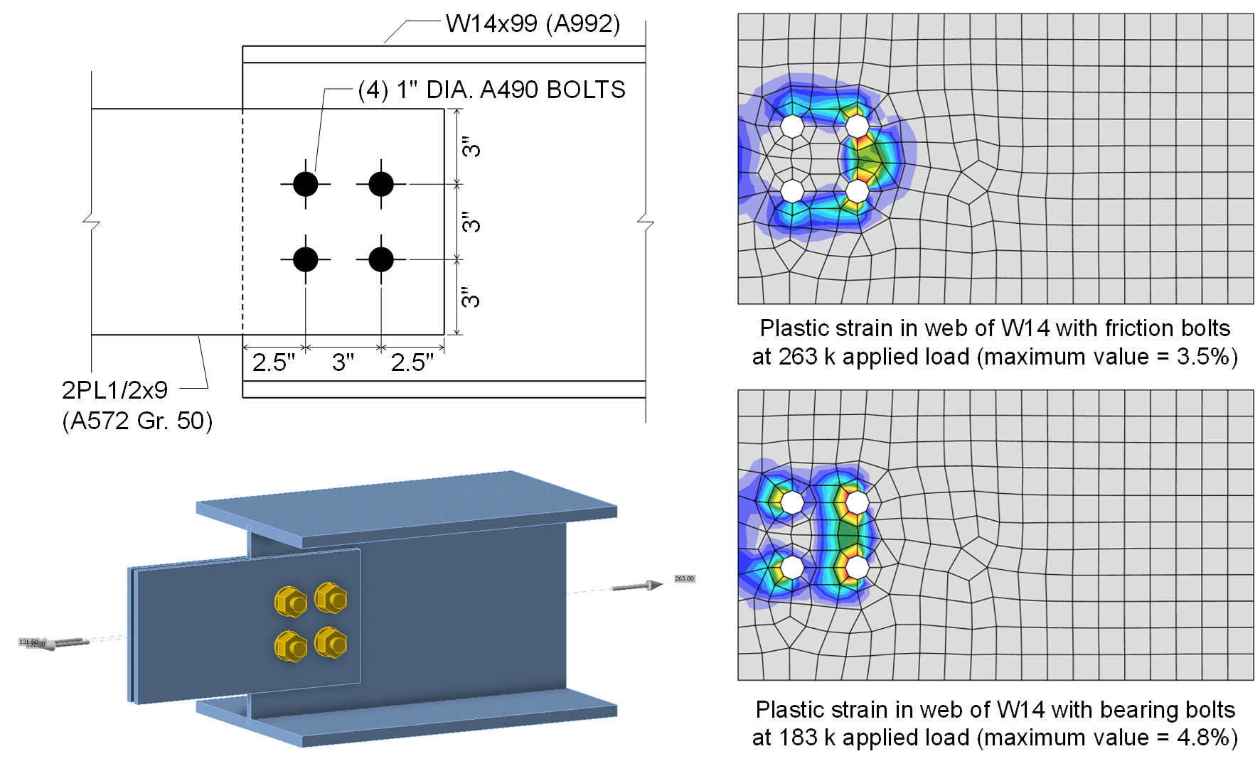
To illustrate this effect, consider the connection shown below between a W14x99 (A992) tension member and two plates. The connection is made with (4) 1 in. diameter A490 bolts in standard holes and Class B surfaces. The design strength of this connection for the limit state of slip is \(\phi R_n = 289\textrm{ kips}\), however, block shear rupture controls the strength of the connection with a design strength of \(\phi R_n = 148 \textrm{ kips}\). When modeled in IDEA StatiCa and the shear force transfer type of the bolts is set to “Friction”, applied loads of up to 263 kips can be applied before the utilization of the bolts reaches 100%. The difference between this strength and the 289-kip design strength for the limit state of slip is because tension in the bolts develops in the model and is conservatively treated as an applied tension in IDEA StatiCa. At 263 kips of applied tension and using “Friction” bolts, the plastic strain in the web is 3.5%, below the 5% limit. When the shear force transfer type for the bolts is set to “Bearing – tension/shear interaction” the maximum applied load decreases to 183 kips with plastic strain in the web controlling. The difference between this strength and the 148-kip design strength for the limit state of block shear rupture is predominantly conservatism in the AISC Specification equation for block shear rupture as described in this article. According to the Canadian standard (CSA S16), the design strength of this connection for the limit state of block shear rupture is 181 kips, approximately equal to the strength from IDEA StatiCa. The figure below shows the plastic strain in the web at the maximum applied load for each shear force transfer type. The distributions of plastic strain are clearly different and demonstrate the larger spread of transfer forces for “Friction” bolts in IDEA StatiCa. Additional discussion can be found in the entry on Slip.
Flexural Yielding
The nominal strength for flexural yielding is defined in AISC Specification (2022) Chapter F for flexural members and Section J4.5 for connecting elements. The nominal strength for the limit state of flexural yielding is generally taken as the specified minimum yield stress, Fy, times the plastic section modulus, Z. In IDEA StatiCa, instead of limiting the required strength to be no more than the available strength (e.g., Mu ≤ ϕMn), members and connecting elements are modeled with shell elements that are assigned a nonlinear stress-strain relationship consisting of a linear elastic region and a linear plastic region, and the plastic strain is limited to 5%.
Modeling members and connecting elements as shell elements results in some simplifications of the physical geometry. For example, shell elements only represent rectangular components thus, fillets are neglected. Additionally, since shell elements are connected at nodes located at the center of thickness there is some overlap at joints of cross-sectional elements. The figure below shows the simplifications for a wide flange shape.
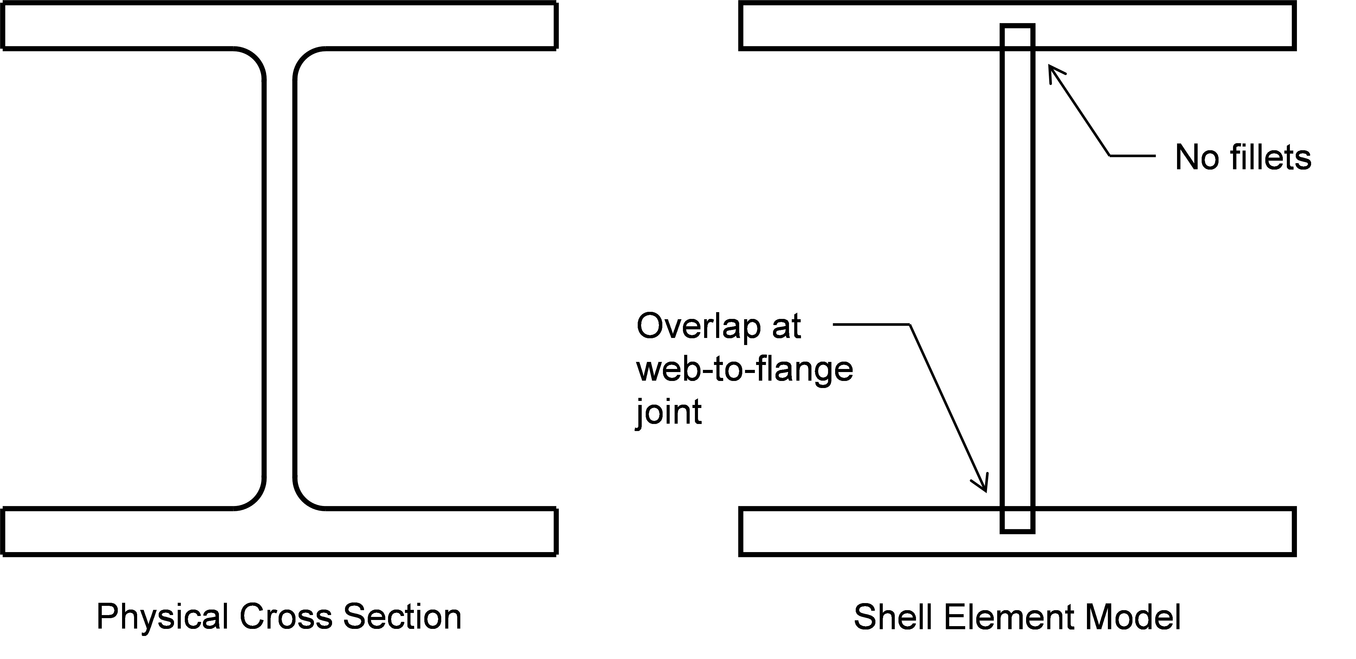
Wide flange shape as modeled in IDEA StatiCa
For a W24x176, the plastic section modulus about the major axis (x axis) listed in the AISC Steel Construction Manual (2023) Table 1-1 is 511 in.3. The plastic section modulus about the major axis of the cross-section formed by the shell elements (with cross-sectional dimensions determined from AISC Manual Table 1-1) is calculated as follows:
\[\frac{t_w(d-t_f)^2}{4}+2b_f t_f \left ( \frac{d-t_f}{2} \right ) = \frac{0.75 \textrm{ in.}(25.2 \textrm{ in.}-1.34\textrm{ in.})^2}{4}+2(12.9\textrm{ in.}) (1.34\textrm{ in.}) \left ( \frac{25.2\textrm{ in.}-1.34\textrm{ in.}}{2} \right ) = 519.2 \textrm{ in.}^3\]
This is 1.6% greater than the plastic section modulus listed in the AISC Manual table.
The stress distribution at the plastic strain limit in IDEA StatiCa will also be different than the idealized stress distribution used to compute Mp. Unlike the idealized stress distribution, the stresses will be lower than Fy near the neutral axis since the plastic strain limit will be reached at a finite curvature. Also, the stresses will be greater than Fy at the extreme fibers of the cross section because a small amount of post-yield hardening is assumed in the stress-strain relationship in IDEA StatiCa.
The overall effect of these minor differences can be observed in a simple splice connection between two W24x176 (ASTM A992) steel shapes. The splice is butt welded (e.g., CJP) and loaded in major axis bending. The design strength of the wide flange according to the AISC Specification (2022) with resistance factor, ϕ = 0.9, is 0.9 × 50 ksi × 511 in.3 = 1916.3 kip-ft. The maximum moment that can be applied to the connection in IDEA StatiCa (version 23.0) is 2000.7 kip-ft., 4.4% greater than the design strength as calculated per the AISC Specification. The plastic strain distribution at the limit is shown in the figure below. As expected, the top and bottom flanges have yielded, but web at the neutral axis remains elastic.
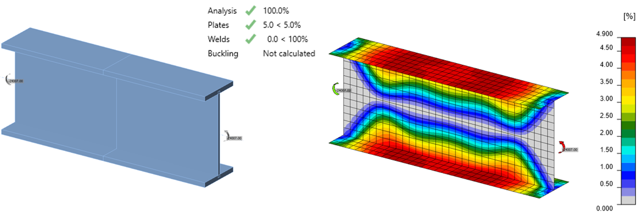
Plastic strain distribution for a W24x176 flexural member at the 5% plastic strain limit
The relationship between applied moment and maximum plastic strain is shown in the figure below. The design flexural strength calculated using the plastic section modulus from the AISC Manual is shown as ϕMp (Manual). The design flexural strength calculated using the plastic section modulus calculated as shown above based on the representation of the section in IDEA StatiCa is shown as ϕMp (IDEA).
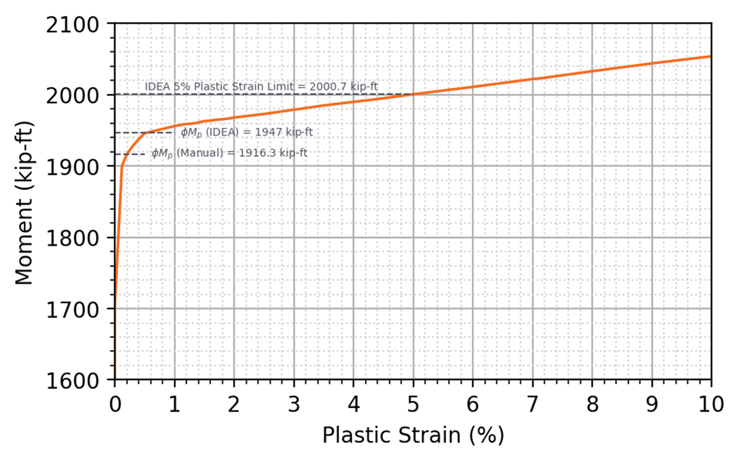
Applied moment vs plastic strain for a W24x176 flexural member
For a wide flange beam, most of the flexural resistance is captured by the in-plane behavior of the shell elements. The out-of-plane behavior of the shell elements can be evaluated through an investigation of plate bending.
For a plate (ASTM A36, Fy = 36 ksi) of width, b = 10 in. and thickness, t = 0.5 in., the plastic section modulus for out-of-plane bending is calculated as Z = bt2/4 = 0.625 in.3, and the design strength, ϕMp, with resistance factor, ϕ = 0.9 is calculated as 0.9 x 36 ksi x 0.625 in.3 = 20.25 kip-in. The geometric simplifications described above for a wide flange section don’t apply to a simple rectangular plate but differences in the stress distribution remain. The maximum moment that can be applied to the plate in IDEA StatiCa (version 23.0) is 19.66 kip-in., 2.9% less than the design strength as calculated per the AISC Specification. The plastic strain distribution for the plate loaded in minor axis bending and a plot of applied moment vs plastic strain are presented in the figures below.
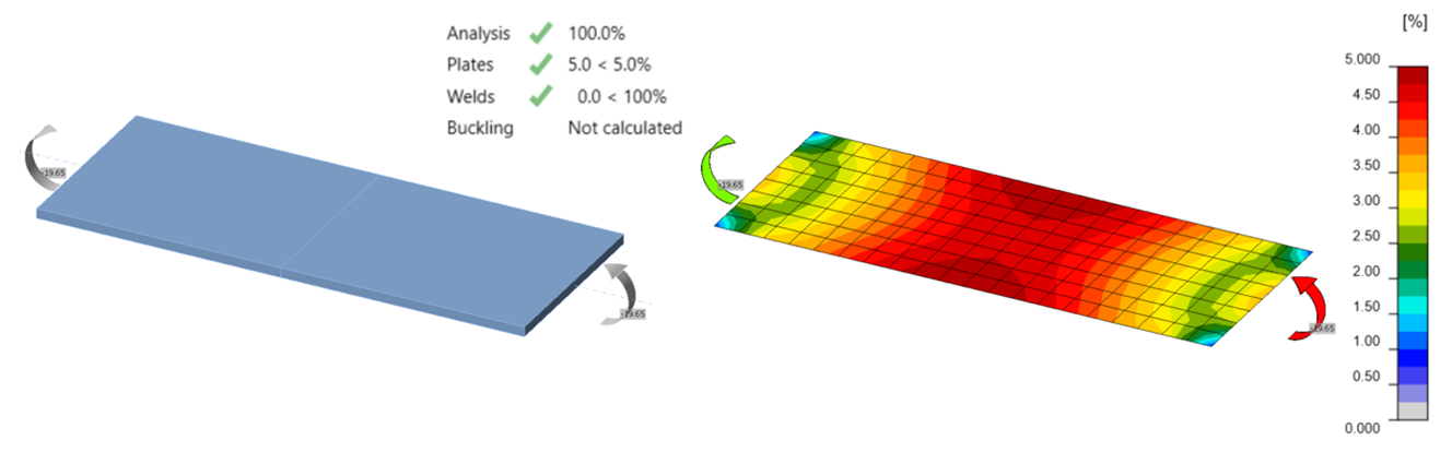
Plastic strain distribution for plate out-of-plane bending at the 5% plastic strain limit

Applied moment vs plastic strain for a plate loaded in minor axis bending
Flexural Rupture
Flexural rupture is among the limit states identified for affected elements of members and connecting elements in flexure in AISC Specification Section J4.5. Flexural rupture can occur when a moment is applied to a cross-section with material removed, such as bolt holes. AISC Specification Chapter J does not define the available strength for the limit state of flexural rupture. AISC Specification Section F13.1 addresses flexural rupture for members with bolt holes in the tension flange, and guidance is provided for flexural rupture of affected and connecting elements in Part 9 of the AISC Manual. Specifically, AISC Manual Equation 9-8 defines the nominal strength for flexural rupture as the product of the specified minimum tensile strength and the net plastic section modulus of the affected or connecting element. The AISC Manual further defines the resistance factor as \(\phi=0.75\) and safety factor as \(\Omega = 2.00\) for flexural rupture.
As with the limit state of tensile rupture, IDEA StatiCa does not evaluate strength equations for flexural rupture. Instead, the limit state of flexural rupture is evaluated using the plastic strain limit. Thus, like for tensile rupture, differences arise because the stress strain relationship used in IDEA StatiCa has minimal strain hardening past yield whereas the design equation uses the tensile strength of the material and because IDEA StatiCa reduces the stress at yielding by a factor of 0.9 (for LRFD) whereas a resistance factor of 0.75 is used for flexural rupture. Additional differences, specific to flexural rupture, result from the use of a plastic section modulus in the design equation, which assumes a uniform stress in either tension or compression. In IDEA StatiCa, stresses are an analysis result and not necessarily uniform.
To examine the net effect of these differences, consider the splice plates tested by Mohr and Murray (2008). They tested 14 specimens altogether; the six tests of the first series with three different bolt patterns are investigated here. The plates were installed between two W27x84 beams. The whole assembly was loaded in four-point bending, subjecting the plate to pure flexure. The dimensions of the largest plates, those with 7 bolts in each vertical row, are shown below. Tests were also performed with 5 and 3 bolts in each vertical row with similar dimensions. The measured yield strength of the plates was Fy = 49.5 ksi, the measured tensile strength of the plates was Fu = 72.1 ksi, and the measured thickness of the plates was t = 0.370 in.
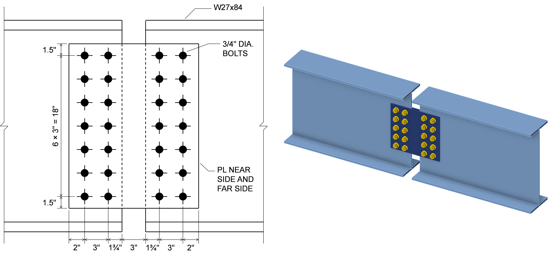
The design strength, \(\phi M_n\), of the plates was computed according to the AISC Specification for the limit state of flexural yielding and the AISC Manual for the limit state of flexural rupture. Measured material and geometric properties were used in these calculations and resistance factors were applied. IDEA StatiCa models of the three connections were also built using measured material and geometric properties of the plates. Resistance factors remained as their default values. Properties of the beams and bolts were increased from nominal values to ensure the failure mode matched that of the experiment. The maximum permitted applied moment from IDEA StatiCa, MIDEA, was determined iteratively. The results of these calculations are shown in the figure below along with the experimental strength, Mexp. The experimental strength was taken as the average of the reported strengths for the two specimens of each bolt pattern. The moments in the figure are for each plate noting that there were two plates for each specimen, one on each side of the beams.
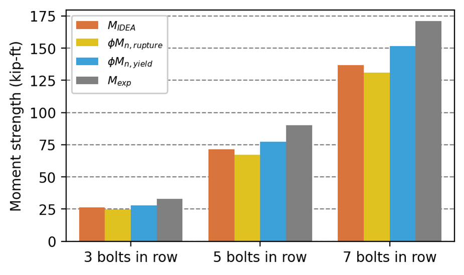
In the physical experiments, all the specimens failed by flexural rupture. Flexural rupture also controls the moment strength of the plates since \(\phi M_{n,rupture} < \phi M_{n,yield}\). IDEA StatiCa, however, does not clearly distinguish between these two limit states; both are evaluated using the 5% plastic strain limit. The plastic strain in the plates at the maximum permitted applied load is shown for the cases with 7 and 3 bolts in each vertical row below.


The maximum permitted applied moment from IDEA StatiCa, MIDEA, is approximately 5% greater than \(\phi M_{n,rupture}\) for these cases, a slightly unconservative result in comparison to the AISC Manual equation. However, MIDEA is approximately 20% lower than Mexp for these cases. While it is expected that MIDEA is less than Mexp since no reduction factor was applied to the experimental results, the difference indicates that there is a safety margin.
Concrete Crushing
At column bases bearing stresses are developed on concrete footings and foundations. AISC Specification (2022) Section J8 provides an equation for the strength of the concrete for the limit state of concrete crushing that is identical to the equivalent provisions in ACI 318 (ACI 2019). The strength depends on the area of steel bearing on a concrete support, the geometry of the concrete support, and the specified compressive strength of concrete.
IDEA StatiCa uses these provisions to evaluate concrete crushing. However, some differences between IDEA StatiCa and traditional hand calculations in the evaluation of concrete crushing arise because of differences in the underlying analysis approach. In hand calculations it is common to assume that the bearing stress is unform over the contact area. In IDEA StatiCa, the stiffness of the concrete footing, the stiffness of the column base, and contact are explicitly modeled resulting in a more physically realistic, non-unform distribution of bearing stress. The bearing area in IDEA StatiCa is computed as the area of steel that is in contact with the concrete and with a bearing stress greater than a cut-off value (the stress cut-off is defined as a ratio to the peak bearing stress with the ratio selectable in the code setup). This can result in a relatively complex shape for the bearing area as shown in the figure below. Nonetheless, the total bearing force, bearing area, and geometrically similar area in the concrete support are computed for use in the code equation.
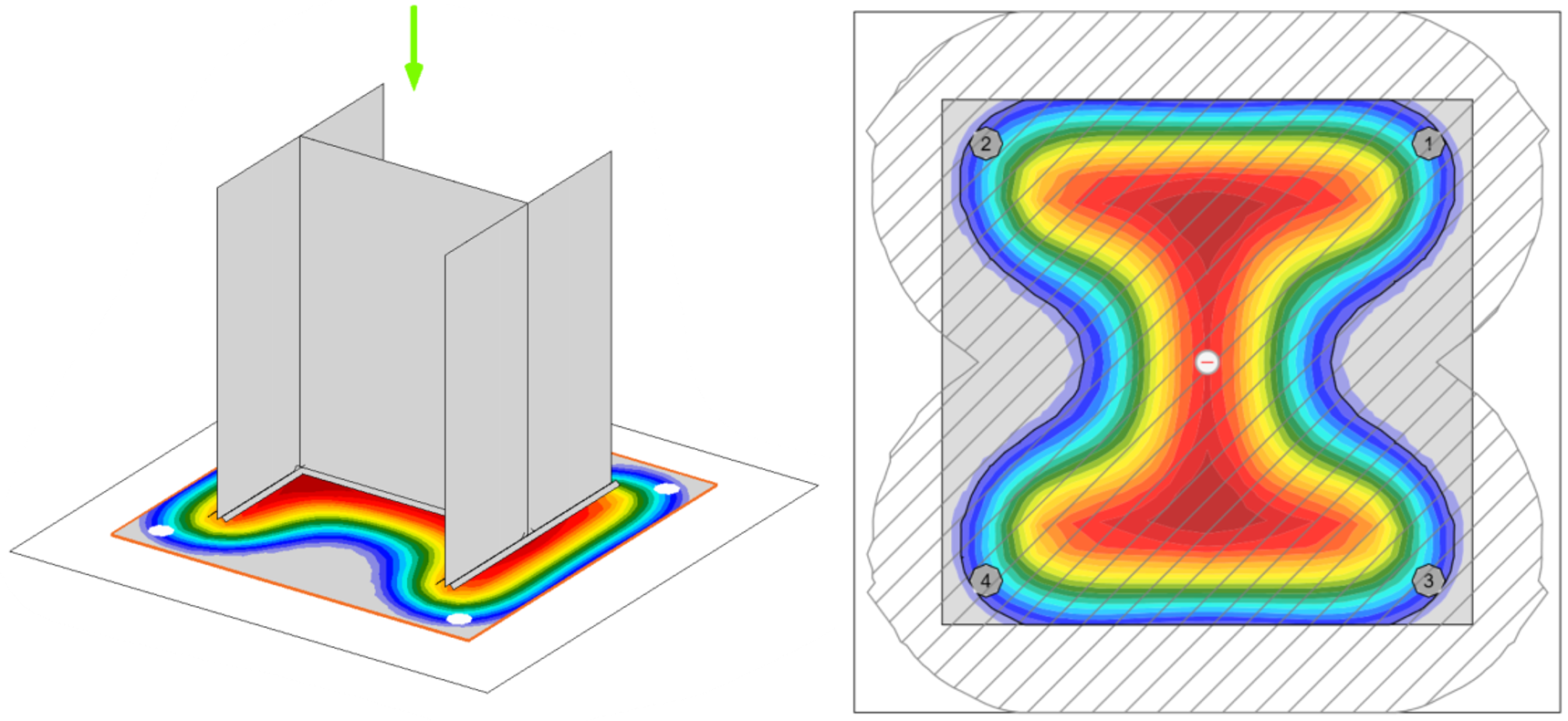
Three-dimensional view (left) and plan view (right) of stress in concrete at the steel-concrete interface of a concentrically loaded base plate connection. The boundary of the bearing area (A1 in AISC Specification Section J8) is shown as a solid black line in the plan view. Note the irregular shape that follows the stress contours and the anchor rod holes. The concrete supporting surface (A2 in AISC Specification Section J8) is shown as the hatched region of the plan view and is similarly irregular.
Additional information can be found in these articles:
- https://www.ideastatica.com/support-center/general-theoretical-background#Structural_model_of_a_concrete_block
- https://www.ideastatica.com/support-center/check-of-components-according-to-aisc
- https://www.ideastatica.com/support-center/check-of-concrete-blocks-according-to-aisc
- https://www.ideastatica.com/support-center/base-plate-connections-aisc
Flange Local Bending
Flange local bending is among the limit states that apply to concentrated forces applied normal to the flange of wide-flange sections and similar built-up shapes. It applies only to tensile concentrated forces. The nominal strength for the limit state of flange local bending is defined in AISC Specification (2022) Section J10.1.
As described in the commentary on Section J10.1, the limit state of flange local bending was originally intended to prevent weld fracture which could occur prematurely because of uneven demands due to flange deformation. However, more recent tests have shown that weld fracture does not occur when flange local bending strength is exceeded, but rather that the flange local bending strength represents a lower bound at which flange deformation could lead to premature flange local buckling or be detrimental to other aspects of member performance. The commentary further notes that while flange deformations can also occur under compressive forces, the AISC Specification does not require flange local bending be checked for compressive forces because it is customary to perform the check for tensile forces only.
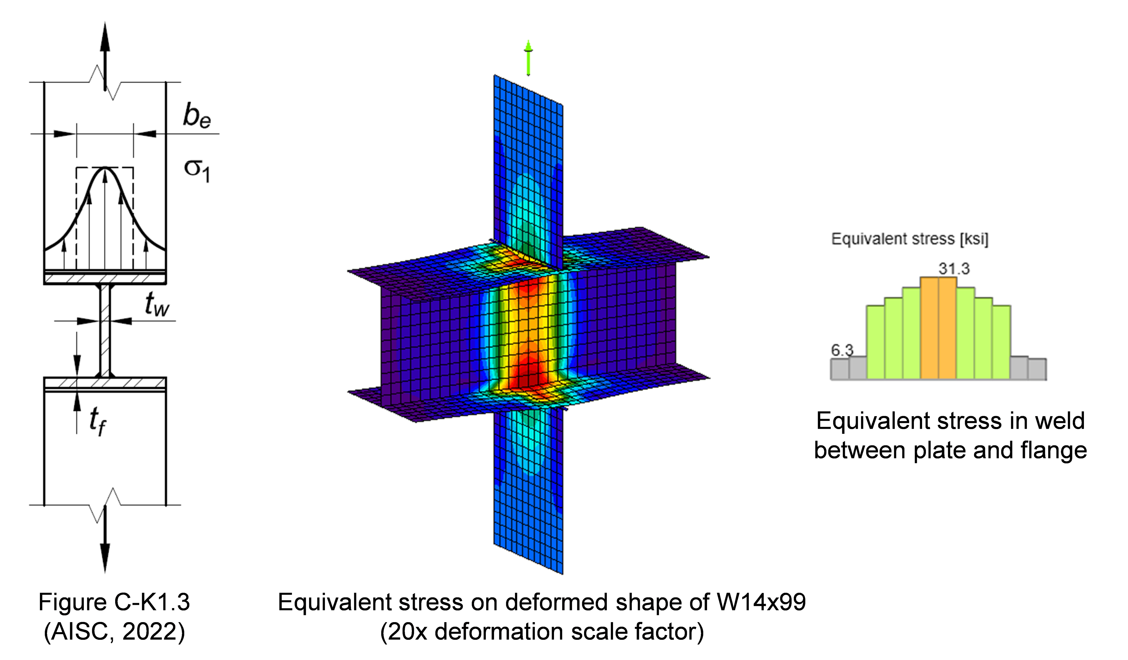
As shown in the figure above, both the uneven stress distribution and flange deformations are explicitly modeled in IDEA StatiCa. Each weld segment is checked independently for strength. Cases like shown in the figure above were examined in the calibration and subsequent validation and verification of the weld model in IDEA StatiCa. However, for shapes other than HSS, local flange deformations are not checked against a limit, their effect on member performance is not evaluated, and their magnitude cannot be directly obtained from the model. As a result, the limit state of flange local bending is not evaluated in IDEA StatiCa. Where the flange local bending controls traditional calculations, significantly higher strengths can be obtained from IDEA StatiCa. Where flange deformations are a concern, it is recommended to evaluate the limit state outside of IDEA StatiCa.
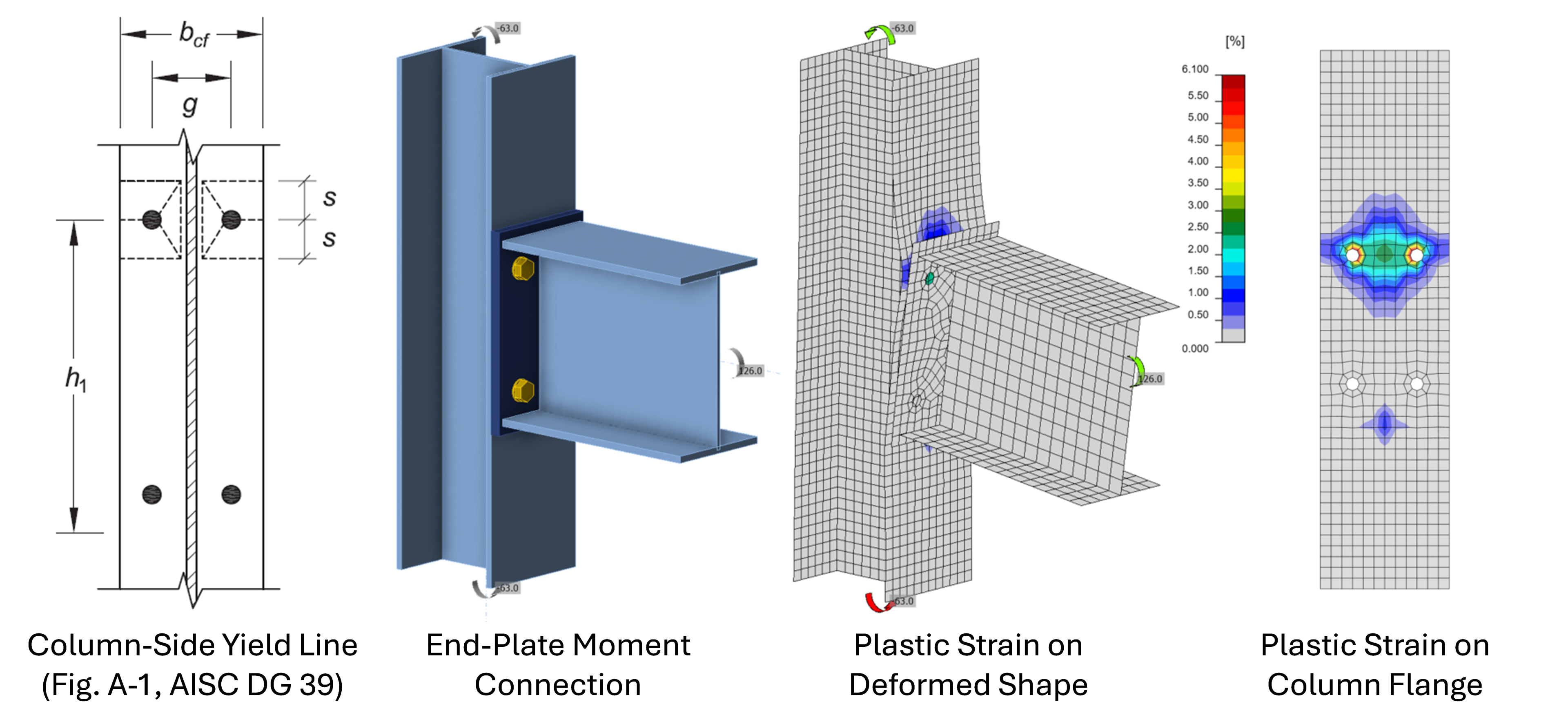
Note that flexural yielding of flanges in bolted connections is considered a separate limit state. In traditional calculations, the available strength is typically determined using yield line theory as described by Dowswell (2011) for general connections or Eatherton and Murray (2023) for end-plate moment connections. IDEA StatiCa captures this limit state through explicit modeling of the flange as shown in the figure below.
Web Local Yielding
Web local yielding is among the limit states that apply to concentrated forces applied normal to the flange of wide-flange sections and similar built-up shapes. The nominal strength equations for web local yielding in AISC Specification Section J10.2 are based on yield of the web over a length equal to the length of bearing plus an assumed spread of the force through the flange. While yielding of the web is modeled explicitly in IDEA StatiCa, several features of the design equations are not. The equations assume a stress gradient of 2.5:1 through the flange and the fillet of rolled shapes. In IDEA StatiCa, the flange is modeled with shell elements and the fillet is neglected, thus the spread of forces depends largely on the constraints between the flange and web. There are two separate equations in AISC Specification Section J10.2 for web local yielding depending on the distance of the force away from the member ends. In IDEA StatiCa, reduction in strength due to proximity to the member end is captured by directly modeling the member. A resistance factor of ϕ = 1.00 and safety factor of Ω = 1.50 apply to the limit state of web local yielding. IDEA StatiCa does not utilize these factors and instead reduces the yield point by a factor of 0.9 for LRFD or by dividing by 1.67 for ASD based on the typical resistance factor and safety factor for yielding.
The overall effect of these differences has been investigated for beam-over-column connections in this article and generic concentrated forces in this report.
Web Compression Buckling
Web compression buckling is among the limit states that apply to concentrated forces applied normal to the flange of wide-flange sections and similar built-up shapes. It applies when a pair of forces compress the web from both flanges at the same location along the length of the member. AISC Specification Section J10.5 provides an equation for the nominal strength for web compression buckling. The equation is based on the elastic buckling strength of a simply supported plate subjected to equal and opposite concentrated forces.
In IDEA StatiCa, design for web compression buckling can be accomplished by ensuring the elastic critical buckling load is sufficiently large (see discussion in the entry on Compressive Yielding and Buckling). Through comparisons to geometric and material nonlinear analysis with imperfections included (GMNIA) an elastic critical buckling load ratio of 3 was determined to be an appropriate lower limit.
Web Panel-Zone Shear Yielding
The available strength for the limit state of panel-zone shear yielding of wide-flange and similar built-up shapes is defined in AISC Specification Section J10.6. Four different equations are provided in this section for the nominal strength. One pair of equations is provided for when the effect of inelastic panel-zone deformation on frame stability is not accounted for in the analysis and another pair for when it is. The first pair of equations limits panel-zone behavior to the elastic range. The second pair of equations provides greater strength; however, plastic deformation of the panel-zone is necessary to achieve greater strength. The additional deformations can significantly increase overall frame deformations and second-order effects. If the potential for inelastic panel-zone deformation is not accounted for in the calculation of member and connection required strengths, then AISC Specification Section J10.6 requires panel-zone behavior to be limited to the elastic range.
In IDEA StatiCa, panel-zone shear yielding is modeled explicitly with nonlinear shell elements and is limited by a plastic strain limit. The limit state of panel-zone shear yielding was explored for extended end plate moment connections in this article and for bolted flange plate moment connections in this article. Using the default plastic strain limit of 5%, the strength from IDEA StatiCa exceeds that from the AISC Specification for when the effect of inelastic panel-zone deformation on frame stability is not accounted for in the analysis. However, reducing the plastic strain limit to a small value (e.g., 0.1%) in IDEA StatiCa enforces essentially elastic behavior and results in strengths that are accurate in comparison to the AISC Specification equations for when the effect of inelastic panel-zone deformation on frame stability is not accounted for in the analysis.
Engineers should know if the effect of inelastic panel-zone deformation on frame stability was accounted for in the analysis to determine required strengths (i.e., not the IDEA StatiCa analysis). And, if it was not, they should limit panel-zone behavior to be essentially elastic.
Connections to HSS Members
AISC Specification (2022) Chapter K includes additional requirements, beyond those of Chapter J, that apply to connections to HSS members and box sections that behave like HSS members. Chapter K is organized by connection type and the requirements are often accompanied by limits of applicability. However, Chapter K does not prohibit the use of connections of other configurations or those outside the limits of applicability.
The limit states described in the tables of Chapter K are evaluated in IDEA StatiCa by explicit modeling and the 5% plastic strain limit. The effects of parameters defined in Section K1, including the effective width for connections to rectangular HSS to account for uneven stress distributions, the chord-stress interaction parameter, and end distance are also modeled explicitly. To increase accuracy, geometric nonlinearity is included in the model by default when a hollow cross-section is used as a bearing member.
The commentary on Chapter K states “When inelastic finite element analysis is used, peak strains in the thick shell (T × T × T) elements should not exceed 0.02/T at the nominal capacity, where T is the thickness in inches.” Neglecting the difference between strain and plastic strain, the limiting value of this recommendation is greater than the 5% used by IDEA StatiCa when the thickness is less than 0.4 in. While the strain limit in the commentary recommendation is more restrictive than the default limit in IDEA StatiCa for thicker tubes, the 5% plastic strain limit is more widely recognized as an acceptable limit for strength design including by the Steel Tube Institute.
Chapter K is based on strength limit states only. As a result, large deformations can occur in connections that meet the requirements of Chapter K. Nonetheless, local out-of-plane deformation of HSS members is checked in IDEA StatiCa against a limit of 3% of the smallest transverse dimension of the cross-section (i.e., diameter or width) based on the requirements of other standards.
As the provisions of Chapter K are based largely on international research and the work of international committees, verifications to other standards are generally informative to US practice. Several verification studies for connections to HSS members are available on the IDEA StatiCa website, including for connections between rectangular hollow sections, circular hollow sections, plate and rectangular hollow sections, and plate and circular hollow sections.
Design Considerations and Requirements
Base de calcul
Le dimensionnement à la résistance selon la Spécification AISC est effectué soit avec les dispositions de dimensionnement par facteurs de charge et de résistance (LRFD), soit avec les dispositions de dimensionnement à la résistance admissible (ASD). Bien que ces deux approches aient des résistances requises et des résistances disponibles différentes, les résistances nominales sont identiques et les dimensionnements finaux devraient être similaires, voire identiques.
| Critère de résistance | Résistance requise | Résistance disponible | Résistance nominale | |
| LRFD | \(R_u \le \phi R_n\) | Ru calculé en utilisant les combinaisons de charges LRFD (p. ex., 1,2D + 1,6L + 0,5Lr) | \(\phi\)Rn également désigné comme la résistance de calcul (\(\phi\) est un facteur de résistance) | Rn |
| ASD | \(R_a \le R_n/\Omega\) | Ra calculé en utilisant les combinaisons de charges ASD (p. ex., D + L) | Rn/Ω également désigné comme la résistance admissible (Ω est un facteur de sécurité) | Rn |
Les résistances requises sont plus élevées en LRFD qu'en ASD en raison des facteurs de charge plus importants dans les combinaisons de charges LRFD. Des différences dans les résistances requises peuvent également apparaître lorsque celles-ci sont calculées par analyse non linéaire et que le niveau de non-linéarité dépend du niveau de chargement. Pour compenser cela dans le dimensionnement à la stabilité, la Spécification AISC exige que tous les effets dépendant des charges soient calculés à un niveau de chargement correspondant aux combinaisons de charges LRFD ou à 1,6 fois les combinaisons de charges ASD. IDEA StatiCa suit une approche différente. Dans IDEA StatiCa, la limite d'élasticité des éléments de coque est prise égale à 0,9Fy pour le LRFD et à Fy/1,67 pour l'ASD, les valeurs 0,9 et 1,67 correspondant respectivement au facteur de résistance et au facteur de sécurité typiques pour les états limites de plastification. Dans la plupart des cas, cela conduit à des charges appliquées maximales admissibles 1,5 fois plus élevées en LRFD qu'en ASD, conformément aux dispositions de la Spécification AISC. Cependant, le module d'élasticité n'est pas réduit dans IDEA StatiCa, que ce soit pour le LRFD ou l'ASD. Par conséquent, le rapport rigidité/résistance diffère entre les deux approches, ce qui entraîne certaines conséquences dans le dimensionnement. Pour le flambement, le rapport limite de charge de flambement élastique diffère entre le LRFD et l'ASD. De plus, lorsque la rigidité d'un assemblage influe sur sa résistance, par exemple dans le cas des assemblages soudés de grande longueur, le rapport des charges appliquées maximales admissibles entre le LRFD et l'ASD peut s'écarter de 1,5. La plupart des études de validation comparant IDEA StatiCa à la Spécification AISC ont été réalisées pour le LRFD.
IDEA StatiCa met en œuvre les dispositions pour l'ASD telles que définies dans la Spécification AISC 2022. Les dispositions de la Spécification AISC 2022 pour l'ASD diffèrent de celles des normes historiques telles que la Spécification AISC de 1989, incluse dans le Manuel AISC de la 9e édition (communément appelé le « livre vert »). Les dispositions historiques pour l'ASD étaient axées sur le comportement élastique et présentaient davantage de différences avec le LRFD. Les dispositions actuelles pour l'ASD sont plus cohérentes avec le LRFD, notamment en ce qui concerne les calculs communs de résistance nominale.
Matériaux en acier de construction
La section A3.1 de la spécification AISC inclut les exigences relatives aux matériaux en acier de construction. Dans cette section, le tableau A3.1 répertorie les matériaux spécifiques qui ont un historique de performances satisfaisantes et sont considérés comme se comportant conformément aux dispositions de la spécification AISC. Les matériaux répertoriés comprennent ceux pour les profilés laminés avec une limite d'élasticité allant jusqu'à 80 ksi et les plaques avec une limite d'élasticité allant jusqu'à 100 ksi. Les matériaux autres que ceux répertoriés dans le tableau A3.1 sont autorisés lorsque leur utilisation est jugée acceptable par l'ingénieur responsable. De nombreux facteurs peuvent affecter la pertinence des matériaux, notamment l'utilisation prévue, les propriétés de résistance dans les directions transversales, la ductilité et la soudabilité.
Compte tenu de la large vérification d'IDEA StatiCa par rapport aux dispositions de la spécification AISC, les matériaux répertoriés dans le tableau A3.1 peuvent également être considérés comme se comportant conformément aux prévisions du logiciel. L'utilisation de matériaux non répertoriés dans le tableau A3.1 n'est pas interdite, mais reste soumise au jugement de l'ingénieur responsable. Le commentaire de la section A3.1 de la spécification AISC comprend une discussion sur les facteurs qui influencent la pertinence des matériaux et des orientations pour évaluer cette pertinence.
Action de levier
Dans les assemblages boulonnés, le contact entre les éléments d'assemblage peut augmenter les efforts de traction au-delà de ceux dus aux seules charges appliquées. Ce phénomène est connu sous le nom d'effet de levier et ne se produit que dans les assemblages soumis à des efforts de traction dans les boulons. Le contact qui augmente les efforts dans les boulons résulte de la déformation de l'élément d'assemblage. Ainsi, l'effet de levier est un paramètre de dimensionnement à prendre en compte tant pour les boulons que pour les éléments d'assemblage.
La rigidité et la résistance relatives des boulons et des éléments d'assemblage gouvernent le comportement. Si les éléments d'assemblage sont rigides par rapport aux boulons, ils se déformeront sans se recourber pour reprendre contact, et aucun effet de levier ne se produira. Dans ce cas, la résistance des boulons gouvernera le dimensionnement. Si les éléments d'assemblage sont faibles par rapport aux boulons, ils plastifieront et transmettront des efforts de levier aux boulons, tout en limitant l'effort dans ces derniers. Dans ce cas, la résistance des éléments d'assemblage gouvernera le dimensionnement. Entre ces deux cas, la résistance des boulons et celle des éléments d'assemblage gouvernent simultanément le dimensionnement.
Des recommandations pour la prise en compte de l'effet de levier dans le dimensionnement sont fournies dans la Partie 9 du Manuel AISC. Les équations présentées dans le Manuel AISC ont été développées pour les cas courants d'un té et de cornières dos à dos, et validées par rapport à des données expérimentales. IDEA StatiCa modélise explicitement la rigidité et la résistance des boulons et des éléments d'assemblage, y compris le contact, de sorte que l'effet de levier est naturellement capturé par l'analyse quelle que soit la configuration spécifique. Une comparaison entre les équations du Manuel AISC et les résultats d'IDEA StatiCa a été réalisée pour les assemblages en té. Une comparaison similaire avec l'approche de dimensionnement de l'effet de levier recommandée dans le Guide to Design Criteria for Bolted and Riveted Joints (Kulak et al. 1987) a également été réalisée. L'effet de levier est illustré dans d'autres exemples de vérification, notamment pour les assemblages de contreventement et les assemblages à platine d'extrémité prolongée avec moment.
Compatibilité des déformations dans les assemblages de grande longueur
Dans les assemblages de grande longueur chargés en bout, la différence d'allongement entre les éléments assemblés est maximale aux extrémités de l'assemblage. Par conséquent, la contrainte dans les boulons et les soudures des assemblages de grande longueur chargés en bout n'est pas uniforme. Étant donné qu'il est courant dans les calculs traditionnels de supposer une contrainte uniforme, la Spécification AISC inclut des réductions de la longueur des soudures de grande longueur chargées en bout et de la contrainte de cisaillement nominale des boulons. La section J2.2b de la Spécification AISC définit la longueur efficace des soudures d'angle chargées en bout, y compris les réductions lorsque la longueur de la soudure dépasse 100 fois la taille de la soudure. Les valeurs de contrainte de cisaillement nominale du tableau J3.2 de la Spécification AISC incluent une réduction de 10 % pour tenir compte des effets de longueur, et une réduction supplémentaire est requise pour les assemblages chargés en bout dont la longueur du schéma de fixation est supérieure à 38 in.
IDEA StatiCa n'applique pas ces réductions directement. Le comportement sous-jacent qui motive ces réductions est plutôt modélisé explicitement. IDEA StatiCa modélise la rigidité des boulons, des soudures et des éléments d'assemblage ; ainsi, la distribution non uniforme des contraintes dans les boulons et les soudures apparaît naturellement. La résistance des boulons et des segments de soudure étant évaluée individuellement, la résistance de l'assemblage qui en résulte est comparable à celle obtenue par les calculs traditionnels. Une comparaison détaillée entre IDEA StatiCa et les résultats issus des calculs traditionnels pour les assemblages de grande longueur chargés en bout est présentée dans cet article.
Compatibilité des déformations dans les groupes de boulons et de soudures chargés de manière excentrique
Les boulons et les soudures dans les groupes chargés de manière excentrique sont soumis à un cisaillement direct ainsi qu'à un cisaillement supplémentaire dû au moment induit. La contrainte résultante dans les boulons ou les soudures varie en amplitude et en direction d'un boulon à l'autre et d'un segment de soudure à l'autre. Comme décrit dans les parties 7 et 8 du manuel AISC, les ingénieurs peuvent utiliser la méthode du centre instantané de rotation ou la méthode élastique pour analyser les groupes de boulons ou de soudures chargés de manière excentrique. Les calculs utilisant la méthode du centre instantané de rotation sont généralement effectués à l'aide de valeurs tabulées fournies dans le manuel AISC.
Dans IDEA StatiCa, la résistance requise des boulons et des segments de soudure est déterminée à partir des résultats de l'analyse non linéaire. Chaque boulon et segment de soudure est modélisé individuellement et l'équilibre est respecté. Les résistances disponibles sont déterminées conformément à la spécification AISC.
La méthode du centre instantané de rotation est également basée sur une analyse non linéaire, mais il existe des différences essentielles entre les analyses non linéaires de la méthode du centre instantané de rotation et IDEA StatiCa. Dans la méthode du centre instantané de rotation, les éléments de liaison sont supposés rigides, ce qui n'est pas le cas pour IDEA StatiCa. La réponse force-déformation des boulons et des soudures diffère également entre les deux méthodes. La réponse force-déformation utilisée dans IDEA StatiCa pour les boulons et les soudures est bilinéaire et est décrite dans les bases théoriques.
Les différences se traduisent généralement par des résistances similaires ou inférieures avec IDEA StatiCa, comme le montre cet article sur les assemblages à platine console. Des comparaisons entre les calculs traditionnels et IDEA StatiCa pour les groupes de boulons chargés de manière excentrique sont également effectuées dans cet article sur les assemblages à platine d'âme simple.
Bolts in Combination with Welds
Accurate strength prediction is more difficult when bolts and welds share load on a common faying surface. The lower ductility of welds in comparison to bolts can lead to brittle fracture before the full strength of the bolt is realized. AISC Specification Section J1.8 allows bolts and welds to be considered as sharing load only in certain circumstances.
According to Section J1.8, bolts can be considered as sharing load with welds only in the design of shear connections on a common faying surface where strain compatibility between the bolts and welds is considered. The section also describes a case with pretensioned high-strength bolts and longitudinal fillet welds where the nominal strength is permitted to be determined as the nominal slip strength plus the nominal weld strength. The bolts and welds must each support a specified proportion of the load and a resistance factor of ϕ = 0.75 or safety factor of Ω = 2.00 applies to the combined joint.
Strength checks for bolts and welds are independent in IDEA StatiCa with no special handling of when bolts and welds share load. Given the explicit modeling of the stiffness of bolts, welds, members, and connecting elements, strain compatibility is always considered in IDEA StatiCa. When bolts and welds share load, the required strength of each is based on their relative stiffness and the available strength is computed as usual. This is true even for tension connections; therefore, it is recommended to not model bolts and welds as sharing load for tension connections and instead only rely on one or the other.
To illustrate the differences between the method provided in AISC Specification Section J1.8 and IDEA StatiCa, consider the connection between plates subjected to tension shown below.
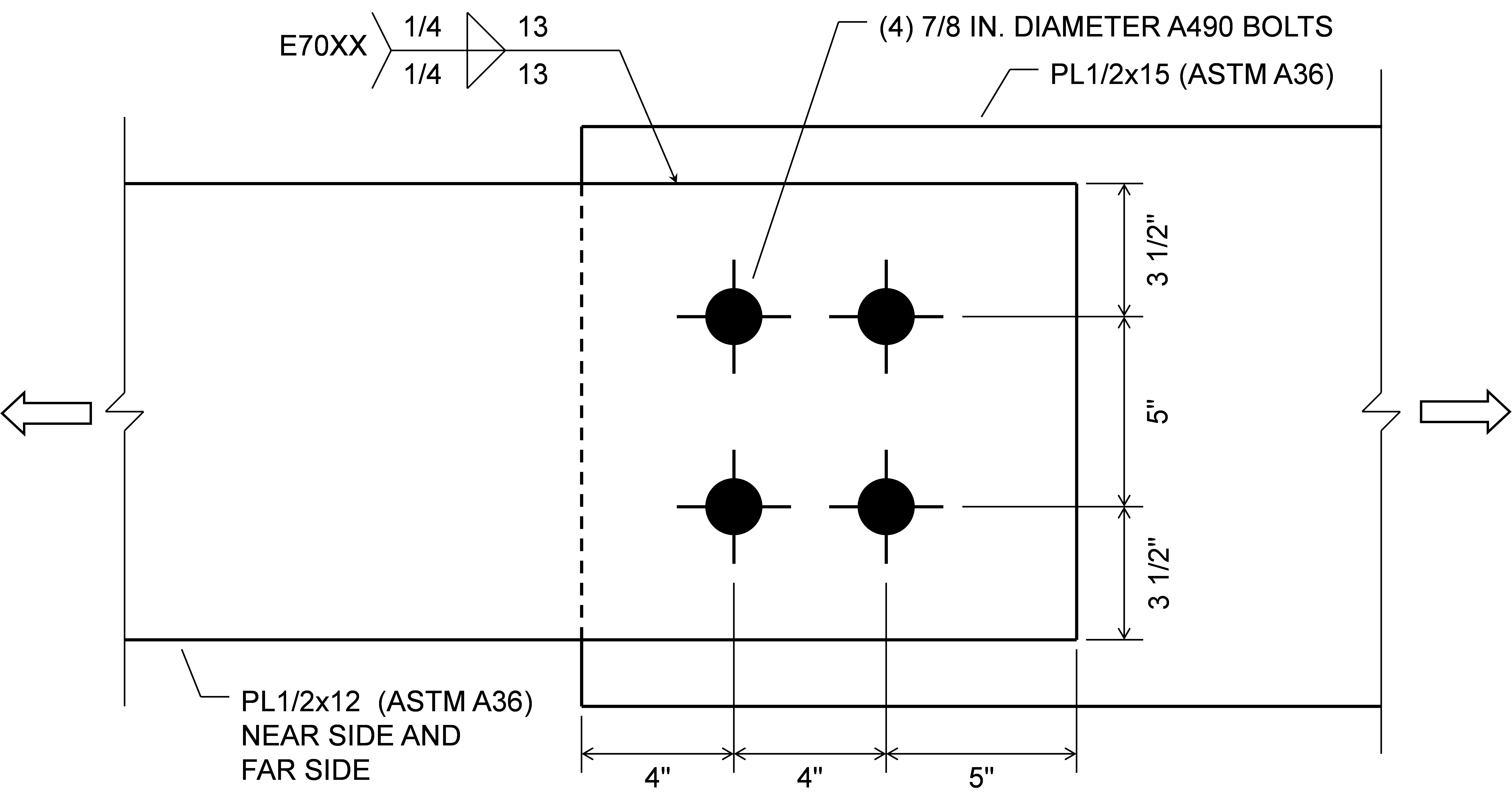
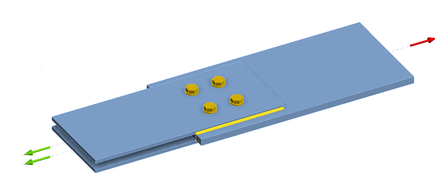
According to the AISC Specification, when the connection is designed as slip-critical, the design strength of the bolts alone is ϕRn = 133 kips (Rn = 133 kips). The design strength of the welds alone is ϕRn = 290 kips (Rn = 386 kips). When combining bolts and welds, the total connection strength is ϕRn = 0.75 (133 + 386) = 389 kips since all requirements in Section J1.8 to allow the summation of bolt and weld strengths are met.
In IDEA StatiCa, the maximum permitted applied tension is 126 kips when the bolts alone are modeled and 277 kips when the welds alone are modeled. The difference between the bolt strength in IDEA StatiCa and the 133-kips design strength is because tension in the bolts develops in the model and is conservatively treated as an applied tension in IDEA StatiCa (see entry on Slip). The difference between the weld strength in IDEA StatiCa and the 277-kips design strength is because of non-uniform demands along the length of the weld in IDEA StatiCa. When both bolts and welds are modeled, the maximum permitted applied tension is 394 kips, with both the bolts and welds showing 100% utilization. This value is closely comparable to the AISC Specification strength of 389 kips.
If the bolts are assumed to be bearing type, the design strength for the bolts according to the AISC Specification is ϕRn = 245 kips. While the AISC Specification permits bolts to be considered as sharing load with welds in shear connections, it does not provide a method to assess the strength when the bolts do not meet the requirements of a slip-critical connection. Therefore, it would be common to assess the strength of this connection as that of the welds alone or ϕRn = 290 kips.
In IDEA StatiCa, when the bolts are modeled as bearing bolts and the welds are not modeled, the maximum permitted applied tension matches the AISC Specification design strength of 245 kips. When the bolts are modeled as bearing bolts and the welds are modeled, the maximum permitted applied tension is 311 kips with weld strength being the controlling limit. This strength is only 12% more than the strength of the welds alone according to IDEA StatiCa. The minor increase in strength with the addition of bearing bolts is because the bolts are less stiff than the welds and thus do not attract much load before the welds reach 100% utilization.
Effet de la Taille du Trou
La section J3.3 de la spécification AISC (2022) décrit l'utilisation de trous standard, surdimensionnés, oblongs courts et oblongs longs pour les boulons dans les assemblages acier structurels. Les trous standard sont les valeurs par défaut dans IDEA StatiCa. Les trous surdimensionnés peuvent être obtenus en modifiant le diamètre du trou dans l'assemblage de boulons. Les trous oblongs peuvent être définis pour les plaques dans l'éditeur de plaques.
La taille du trou affecte plusieurs aspects du comportement, et certaines exigences de conception sont basées sur la taille du trou.
- Le matériau retiré pour les trous de boulons affecte l'aire nette. Cet effet est pris en compte explicitement dans IDEA StatiCa par la définition du modèle d'éléments de coque pour les éléments et les pièces de connexion. Cependant, le supplément de 1/16 po. pour les dommages requis par la section B4.3b de la spécification AISC n'est pas automatiquement implémenté (voir Détermination de l'aire nette)
- La taille du trou affecte la distance libre utilisée pour déterminer la résistance à l'arrachement. Cet effet est pris en compte explicitement dans IDEA StatiCa en calculant la distance libre en fonction de la géométrie du matériau assemblé et de la direction de la force dans le boulon individuel.
- Les trous surdimensionnés ne sont pas autorisés dans les assemblages de type appui. IDEA StatiCa ne vérifie pas cette exigence et autorisera l'utilisation du transfert d'effort par cisaillement en appui avec des trous surdimensionnés.
- Le facteur de résistance pour l'état limite de glissement dépend du type de trou. IDEA StatiCa n'ajuste pas automatiquement le facteur de résistance en fonction du type de trou. Le facteur de résistance peut être défini manuellement dans la configuration du code.
La taille du trou peut affecter la réponse charge-déformation du boulon. Le modèle charge-déformation du boulon utilisé dans IDEA StatiCa ne dépend pas de la taille du trou, mais le transfert par cisaillement est supposé nul dans la direction longitudinale des trous oblongs.
Sous-épaisseur de laminage
La variation de longueur des éléments peut entraîner des différences significatives dans les dimensions utilisées pour la conception des assemblages. Dans plusieurs calculs des exemples de conception AISC, une tolérance de 1/4 po. est soustraite d'une longueur pour tenir compte d'une éventuelle sous-épaisseur de laminage. IDEA StatiCa ne prend pas automatiquement en compte la sous-épaisseur de laminage éventuelle, mais celle-ci peut être considérée en définissant manuellement l'assemblage avec la sous-épaisseur supposée.
Contact et Frottement
L'acier ne peut physiquement pas traverser l'acier, pourtant c'est le comportement par défaut dans les analyses par éléments finis. Les surfaces de contact doivent être définies pour empêcher le chevauchement des matériaux lors de la déformation. Le contact surface à surface est défini automatiquement avec les opérations de groupe de boulons. Le contact surface à surface peut être défini avec l'opération « Groupe de boulons/contact ». Le contact bord à bord ou bord à surface peut être défini avec l'opération « Soudure générale ou contact ».
Toutes les surfaces de contact potentielles ne sont pas définies automatiquement par IDEA StatiCa. Il est donc important que l'utilisateur ait une bonne compréhension du comportement attendu de l'assemblage et examine la forme déformée pour confirmer que l'assemblage est modélisé et se comporte comme prévu.
L'appui par contact peut être un moyen efficace de transfert des efforts dans un assemblage si celui-ci a été détaillé et si les surfaces sont soigneusement préparées de manière à ce que l'appui existe (Muir 2015). Étant donné qu'un détaillage particulier est nécessaire pour garantir l'efficacité de l'appui par contact, le contact bord à bord et bord à surface n'est pas défini automatiquement dans IDEA StatiCa, mais peut être défini manuellement à l'aide de l'opération « Soudure générale ou contact ». Les éclisses de poteau boulonnées sont un exemple où la définition du contact bord à bord entre les éléments réduira les sollicitations dans les boulons, ce qui donnera un assemblage plus efficace. L'utilisation de l'appui par contact peut également être efficace en combinaison avec des soudures entre poteaux et platines de base. Les soudures, par défaut, ne sont pas définies avec contact et sont donc également vérifiées pour les efforts de compression. La combinaison des opérations de soudure et de contact peut permettre l'utilisation de soudures plus petites. Les soudures sont rigides et attireront les charges même lorsqu'elles sont combinées avec un contact, mais les sollicitations dues aux efforts de compression dépasseront rarement la capacité, même si la taille de la soudure est réduite.
Le frottement aux surfaces de contact acier sur acier est négligé de manière conservative dans IDEA StatiCa, à l'exception des boulons désignés pour transférer les efforts de cisaillement par frottement (c'est-à-dire les boulons à glissement contrôlé). La prise en compte du frottement uniquement lorsque des boulons précontraints fournissent l'effort de serrage est également typique des calculs traditionnels. Cependant, certaines différences de résultats entre IDEA StatiCa et les calculs traditionnels peuvent survenir en raison du frottement. Par exemple, la Section J3.10 de la Spécification AISC définit un facteur de réduction à appliquer à la résistance au glissement lorsqu'un assemblage à glissement contrôlé est soumis à une combinaison de traction et de cisaillement. Le facteur de réduction est basé sur l'effort de traction appliqué à l'assemblage. IDEA StatiCa n'a aucun moyen de quantifier quelle part de l'effort de traction dans un boulon est due à la charge appliquée par rapport à d'autres sources telles que l'effort de levier. Si l'effort de levier induit une traction dans un boulon à glissement contrôlé, alors la résistance au glissement sera réduite dans IDEA StatiCa. La résistance au glissement selon les calculs traditionnels ne serait pas réduite. Une investigation détaillée de cette différence est décrite pour les assemblages en té dans cet article.
Détermination de la section nette
La section B4.3b de la spécification AISC (2022) exige que la largeur d'un trou de boulon soit prise égale à la dimension nominale du trou augmentée de 1/16 po lors du calcul de la section nette en traction ou en cisaillement. L'application de cette exigence réduit la section nette afin de tenir compte des dommages éventuels autour d'un trou de boulon lors des opérations de perçage ou de poinçonnage. Cette exigence affecte les états limites tels que la rupture par traction de la section nette et la rupture par cisaillement en bloc, mais n'affecte pas l'état limite d'arrachement au niveau des trous de boulons.
Dans IDEA StatiCa, les assemblages de boulons par défaut ont un diamètre de trou égal à la dimension nominale du trou. Par conséquent, bien que le 1/16 po puisse être ajouté manuellement au diamètre du trou de boulon en modifiant l'assemblage de boulons, cette exigence n'est pas automatiquement prise en compte dans IDEA StatiCa. Si le diamètre du trou de l'assemblage de boulons est augmenté, le diamètre augmenté s'appliquera à tous les aspects de l'analyse, y compris l'évaluation de l'arrachement. Une discussion supplémentaire sur la façon dont la taille du trou affecte les résultats dans IDEA StatiCa peut être trouvée dans l'entrée sur l'effet de la taille du trou.
La section B4.3b de la spécification AISC (2022) inclut également des dispositions pour la détermination de la section nette lorsqu'une chaîne de trous de boulons s'étend à travers une pièce selon une ligne diagonale ou en zigzag. Pour ces cas, la largeur nette de la pièce est obtenue en déduisant de la largeur brute la somme des diamètres (incluant le 1/16 po pour les dommages) de tous les trous de la chaîne, et en ajoutant, pour chaque espacement de jauge dans la chaîne, la quantité s2/4g, où
g = espacement transversal centre à centre (jauge) entre les lignes de jauge des éléments de fixation
s = espacement longitudinal centre à centre (pas) de deux trous de boulons consécutifs quelconques
La largeur nette résultante est différente de la longueur de la surface de rupture (c'est-à-dire la ligne pointillée rouge dans la figure ci-dessous) et tient compte de la combinaison de la traction et du cisaillement le long du plan incliné. Étant donné qu'IDEA StatiCa ne calcule pas explicitement la section nette, les dispositions relatives à la largeur nette ne sont pas implémentées dans le logiciel. Cependant, le risque de rupture le long d'une ligne diagonale ou en zigzag de boulons, incluant l'interaction de la traction et du cisaillement le long du plan incliné, est capturé explicitement par la modélisation des éléments assemblés.
L'effet du décalage des lignes de boulons peut être observé dans un assemblage d'éclissage simple. Une plaque d'essai est boulonnée entre deux plaques de réaction et chargée en traction. L'épaisseur de la plaque d'essai est de 1/2 po et l'épaisseur de chaque plaque de réaction est de 3/8 po. Toutes les plaques ont une largeur de 6 po et sont conformes à l'ASTM A572 Gr 50 (Fy = 50 ksi, Fu = 65 ksi). L'assemblage comporte (6) boulons A325 de 7/8 po de diamètre en deux lignes décalées. L'espacement entre les boulons d'une même ligne est de 3 po, la jauge, g, est de 3 po, et la distance au bord est de 1,5 po. Le décalage entre les deux lignes de boulons est mesuré par la dimension s.

Une vue tridimensionnelle de l'assemblage avec s = 1,5 po est présentée dans la figure ci-dessous.
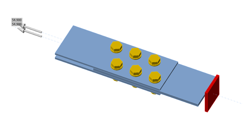
Des analyses ont été effectuées pour des assemblages avec la dimension s variant de zéro (c'est-à-dire sans décalage) à 3 po par incréments de 0,5 po. La résistance selon la spécification AISC a été calculée en utilisant les dispositions de la section B4.3b. L'état limite de rupture par traction le long de la ligne en zigzag représentée par une ligne pointillée rouge dans la figure ci-dessus a été déterminant pour tous les cas. La résistance selon IDEA StatiCa a été déterminée de manière itérative par analyse contrainte-déformation en ajustant la charge appliquée en entrée à une valeur que le programme juge sûre, mais si elle est augmentée d'une petite quantité (0,1 kip), le programme la jugerait non sûre. La limite de déformation plastique de 5 % a été déterminante pour tous les cas. Les résultats des analyses sont présentés dans la figure ci-dessous.
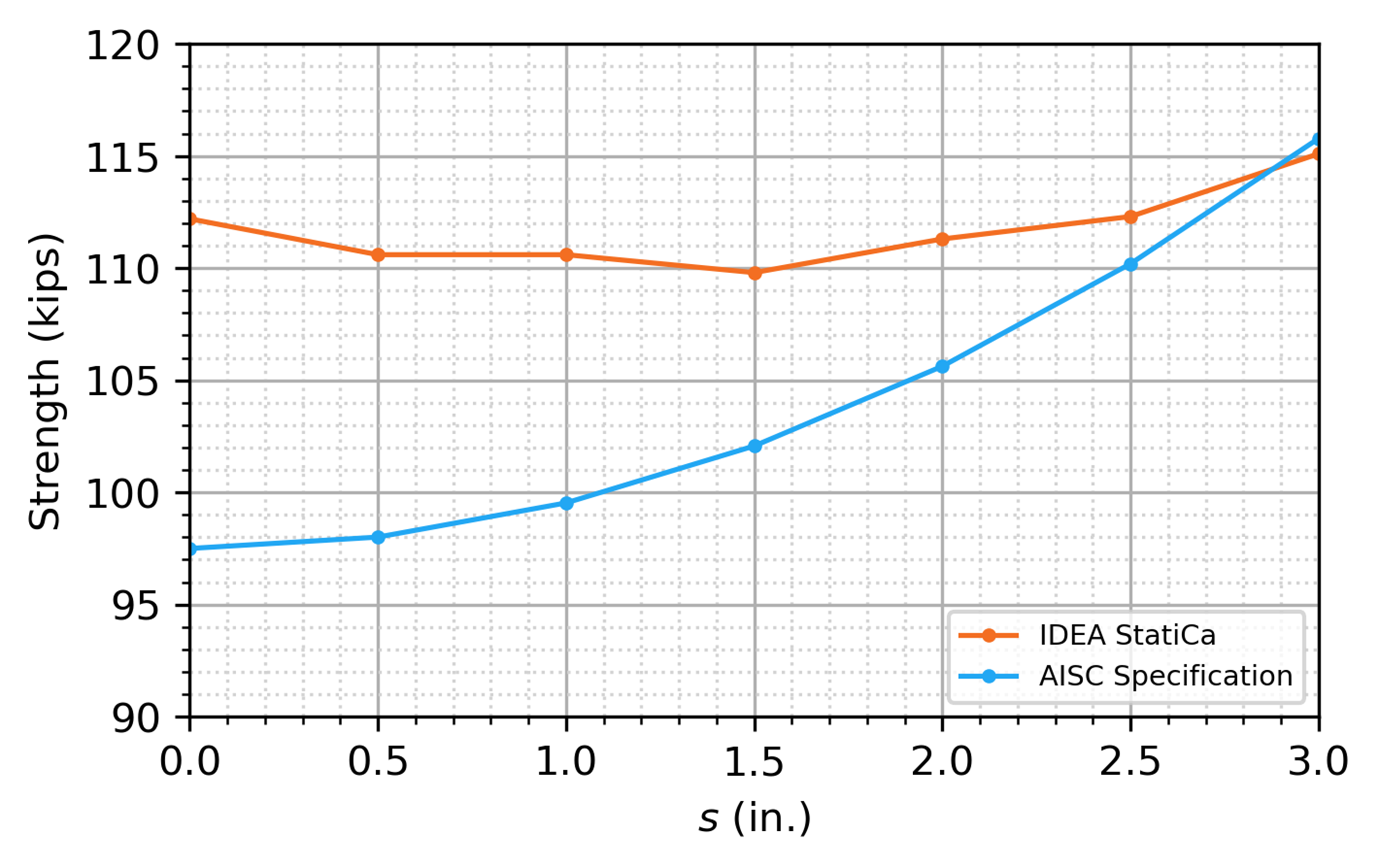
Les résultats de la spécification AISC montrent une tendance claire d'augmentation de la résistance avec la dimension s. Les résultats d'IDEA StatiCa montrent une sensibilité moindre à la dimension s et la résistance est supérieure à celle de la spécification AISC pour tous les cas sauf celui avec s = 3 po. Cependant, le mode de rupture en zigzag attendu est capturé par le modèle, comme le démontre la figure ci-dessous qui montre la déformation plastique dans la plaque d'essai à la charge appliquée maximale autorisée.

Exigences de dimensionnement des soudures d'angle
La section J2.2b de la spécification AISC (2022) inclut des limitations pour les soudures d'angle.
Les points (a)-(c) de la section J2.2b spécifient des limitations géométriques sur la taille et la longueur minimale des soudures d'angle. Ces limitations sont vérifiées lors du calcul si l'option « Détails constructifs » est cochée dans la « Configuration normative ». Les limitations spécifiques vérifiées sont décrites dans cet article. Une soudure ne passera pas la vérification normative en raison d'une erreur de détail constructif si l'une des limitations n'est pas satisfaite. Les dimensions proches ou à la limite peuvent ne pas être évaluées comme prévu en raison de la précision numérique ou des arrondis.
Le point (d) de la section J2.2b spécifie la longueur efficace des soudures d'angle, y compris les réductions pour les soudures d'angle à chargement d'extrémité de grande longueur. IDEA StatiCa ne calcule pas la longueur efficace des soudures d'angle et n'applique donc pas les dispositions de cette section, mais l'effet de la distribution non uniforme des contraintes sur la résistance des soudures d'angle à chargement d'extrémité est pris en compte par la modélisation explicite de la rigidité de la soudure et du matériau assemblé. Voir cet article pour une analyse détaillée de cette disposition.
Les points (e)-(i) de la section J2.2b spécifient des limitations qui ne sont pas vérifiées par IDEA StatiCa et qui, le cas échéant, doivent être évaluées séparément par l'ingénieur.
Épaisseur de paroi de calcul pour les profils creux (HSS)
La section B4.2 de la spécification AISC (2022) exige que l'épaisseur des parois soit prise comme l'épaisseur de paroi de calcul, t, dans les calculs de résistance pour les profils creux (HSS). L'épaisseur de paroi de calcul est égale à l'épaisseur nominale, tnom, pour les sections en caisson et les HSS produits conformément à l'ASTM A1065/A1065M ou à l'ASTM A1085/A1085M. L'épaisseur de paroi de calcul est égale à 0,93 fois l'épaisseur nominale de la paroi (c'est-à-dire t = 0,93tnom) pour les autres normes approuvées pour utilisation par la spécification, y compris l'ASTM A500/A500M. L'ASTM A500 Gr. C est la spécification de matériau préférée aux États-Unis pour les HSS rectangulaires et circulaires (Tavarez 2022).
IDEA StatiCa n'ajuste pas automatiquement l'épaisseur de paroi des sections transversales HSS en fonction du matériau. L'utilisateur doit donc être conscient de cette exigence et s'assurer que l'épaisseur appropriée est assignée.
Lors de la définition de la section transversale dans IDEA StatiCa, les sections transversales prédéfinies de la catégorie intitulée « HSS (AISC 15.0 - A1085, A1065) » ont une épaisseur de paroi égale à l'épaisseur nominale de la paroi, et celles de la catégorie intitulée « HSS (AISC 15.0 - A500, A501, A618, A847) » ont une épaisseur de paroi égale à 0,93 fois l'épaisseur nominale de la paroi.
References
AISC (2022), Specification for Structural Steel Buildings, American Institute of Steel Construction, Chicago, IL.
AISC (2023), Steel Construction Manual, 16th Edition, American Institute of Steel Construction, Chicago, IL.
Dowswell, B. (2011). “A Yield Line Component Method for Bolted Flange Connections.” Engineering Journal, AISC, 48(2nd Quarter), 93–116.
Dowswell, B. (2015). “Plastic Strength of Connection Elements.” AISC Engineering Journal, 52(1st Quarter), 47–66.
Eatherton, M. R., and Murray, T. M. (2023). End-Plate Moment Connections. Design Guide 39, American Institute of Steel Construction, Chicago, Illinois.
Kulak, G. L., Fisher, J. W., and Struik, J. H. A. (1987). Guide to Design Criteria for Bolted and Riveted Joints, Second Edition. John Wiley & Sons, Inc.
Miazga, G. S., and D. L. Kennedy. (1989), “Behaviour of fillet welds as a function of the angle of loading,” Canadian Journal of Civil Engineering, 16 (4): 583–599.
Muir, L. (2015), “Bear It and Grin” Modern Steel Construction, AISC. (December).
Mohr, B. A., and Murray, T. M. (2008). “Bending Strength of Steel Bracket and Splice Plates.” Engineering Journal, AISC, 45(2), 97–106.
Tavarez, J. (2022), “Are You Properly Specifying Materials?” Modern Steel Construction, AISC. (June), 16-22.