
ETABS BIM link for steel connection design (AISC)
1 How to activate the link
- Install the latest version of IDEA StatiCa
- Make sure you are using a supported version of ETABS – updates are published in the BIM section of the main website
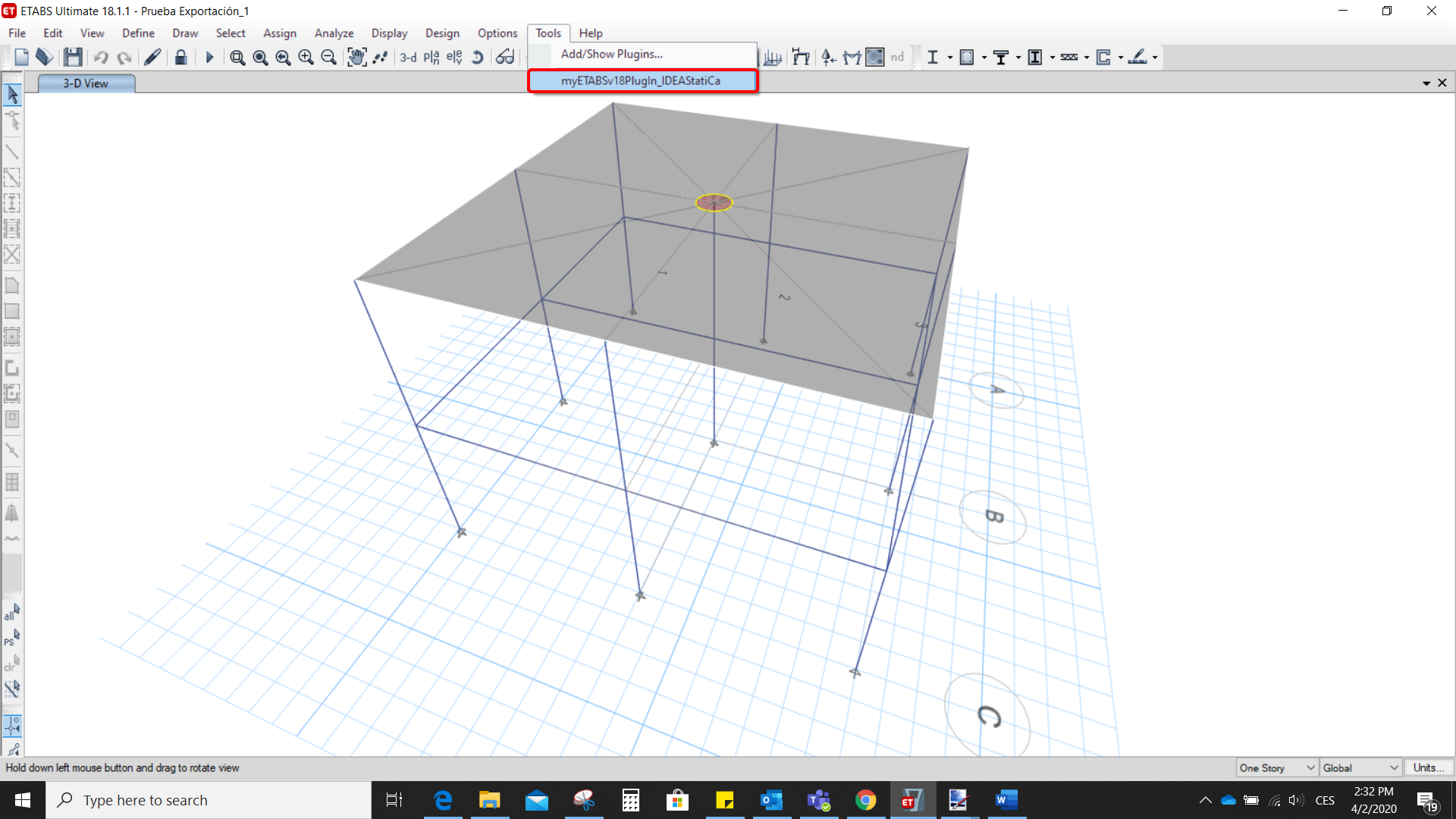
After installation of both programs, start ETABS and Click Tools > Add/Show Plugins to open the Plugin Manager dialog. This option lets you install and add add-ins (programs) to the appropriate places in the ETABS menu.
Browse for
C:\Program Files\IDEA StatiCa\StatiCa 20.0\ETABSv18PlugIn_IDEAStatiCa.dll
and click Add

2 How to use the link
Open the attached project in ETABS and run the analysis.
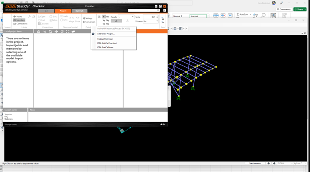
Go to the menu item Tools and run the export command you have just defined.
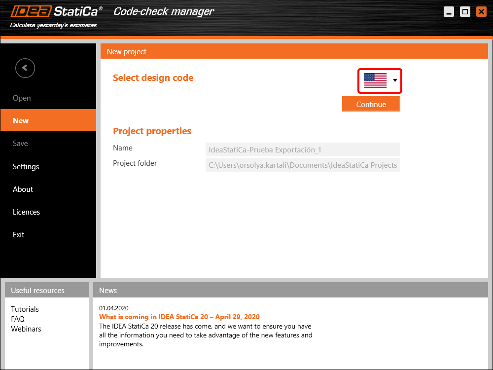
The Code-check manager opens and at first, you need to choose the code.
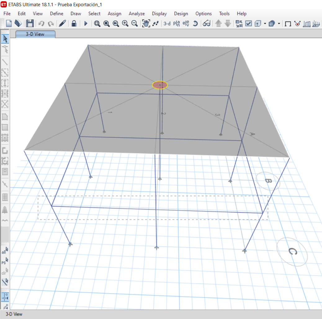
Then you can make a rectangular selection in the ETABS project to choose which joints you want to export. You can export more joints at once using the multiple selections.
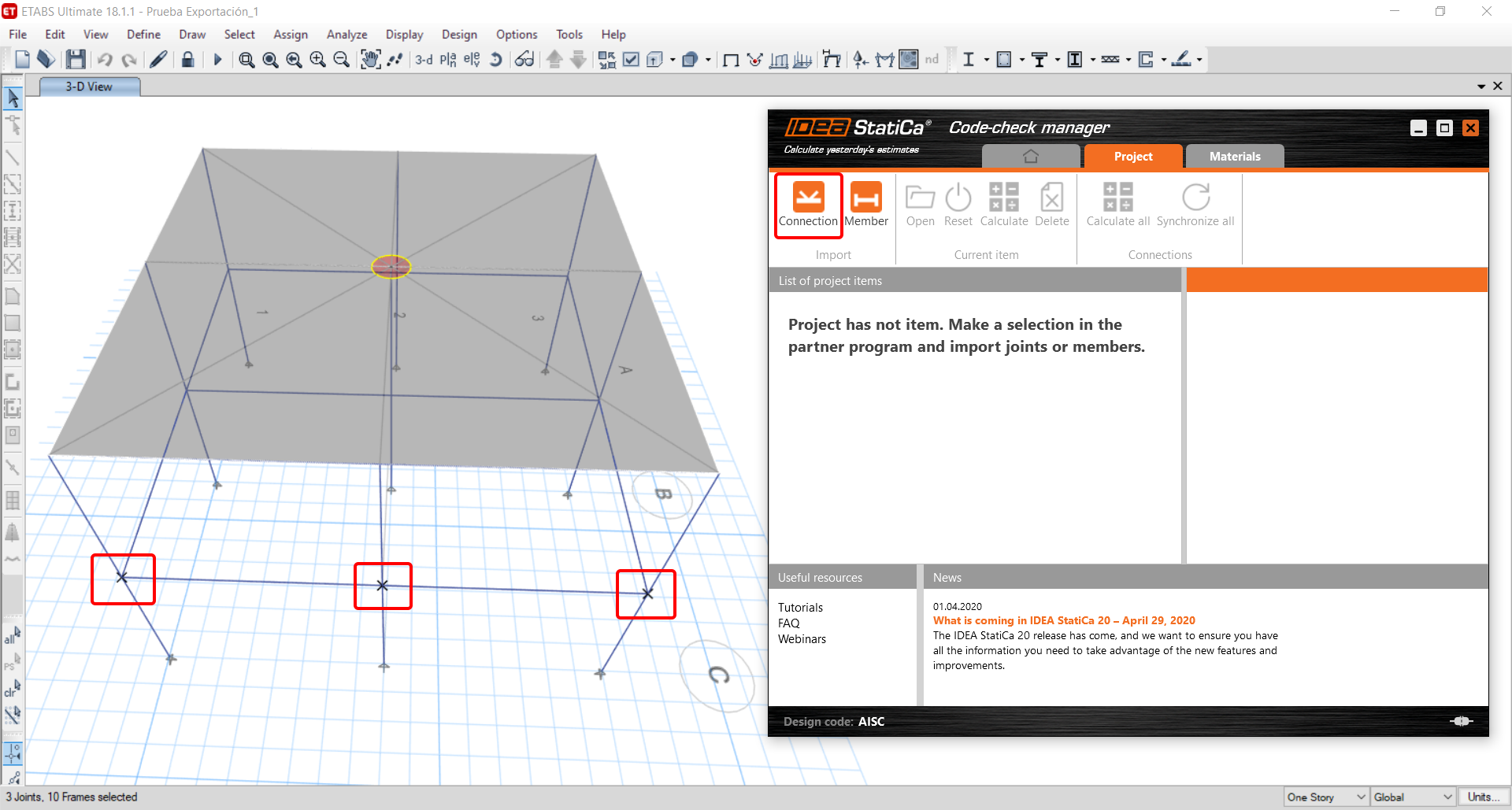
If the joints are selected, you can click on the Connection button in the Code-check manager. With this, all the selected joints from ETABS will be imported into the Code-check manager.
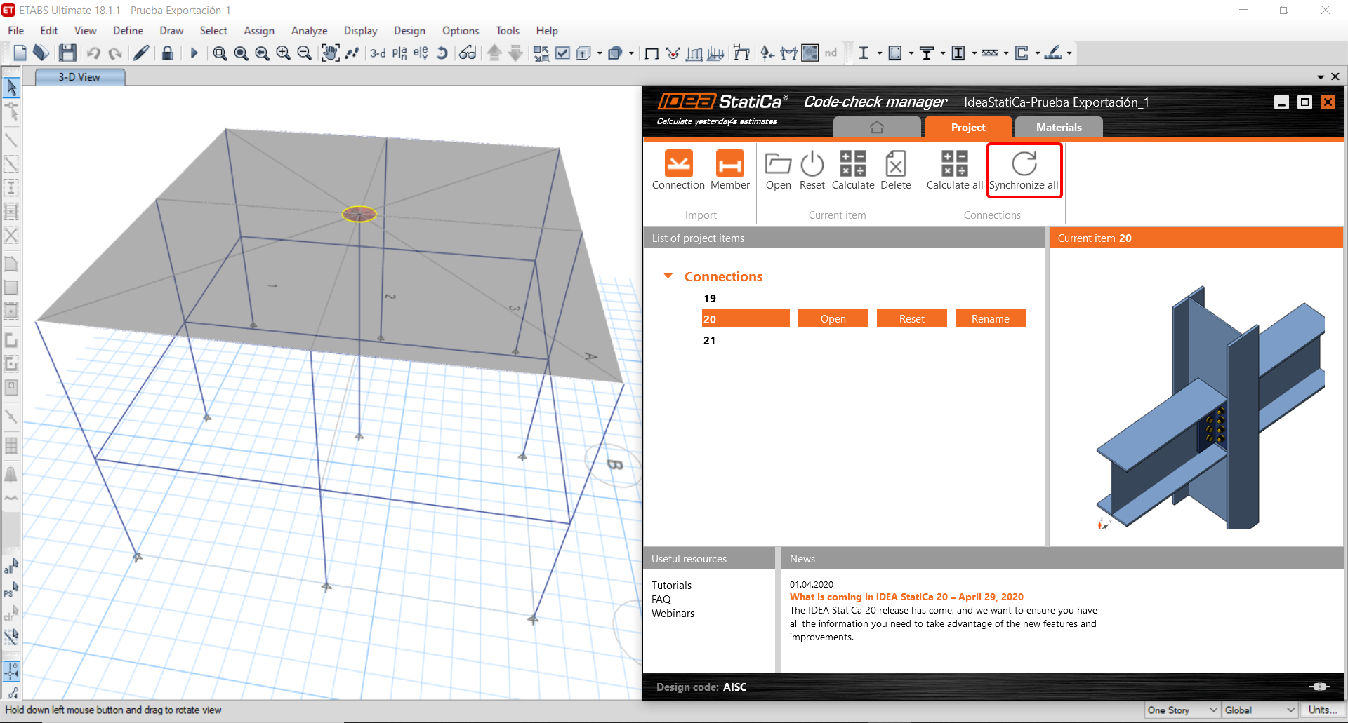
The next thing you need to do is to configure the joints in the Code-check manager. In this tutorial, you will only focus on one of the three imported joints, but the process would be the same for all of them.
You click on the joint on the left side (joint 20). On the right side, you can see the scheme of the joint, you can set the bearing member and merge the continuous members. After that, click on the Finish button to complete the configuration of the joint.
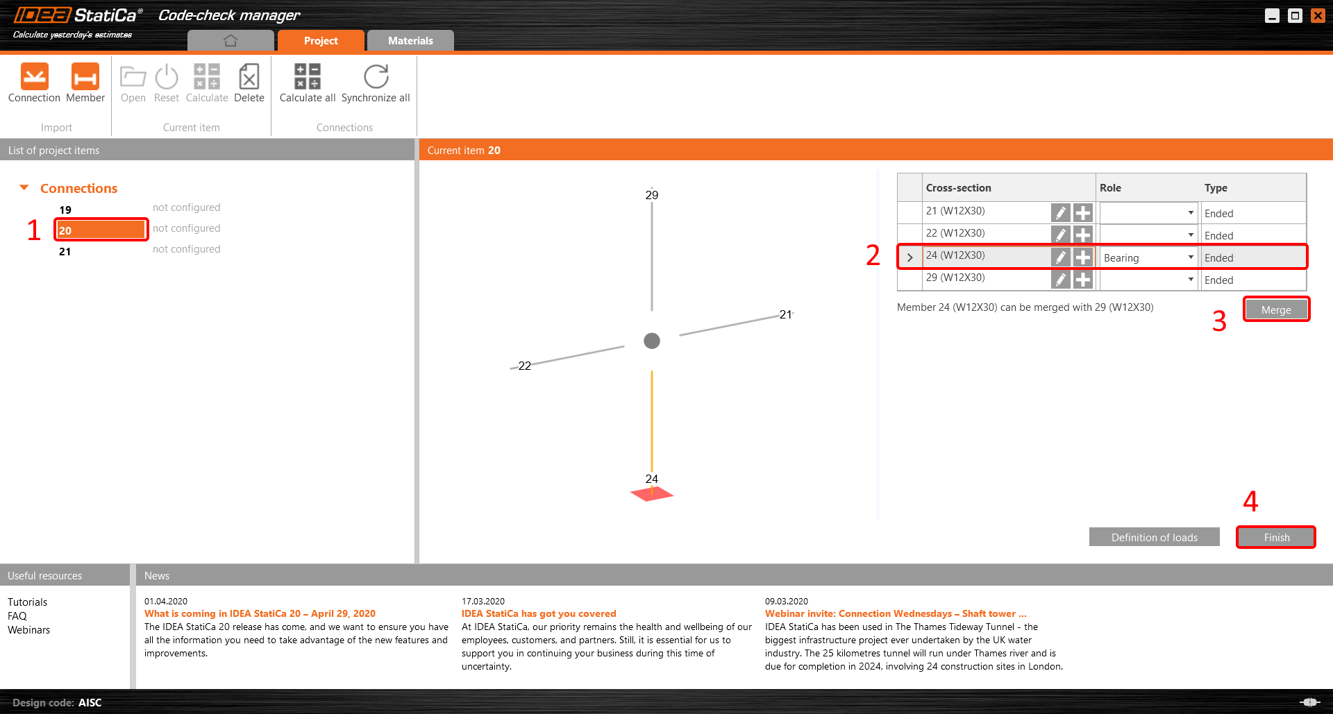
The joint is now ready to be opened in IDEA StatiCa Connection for the CBFEM analysis.

3 Design
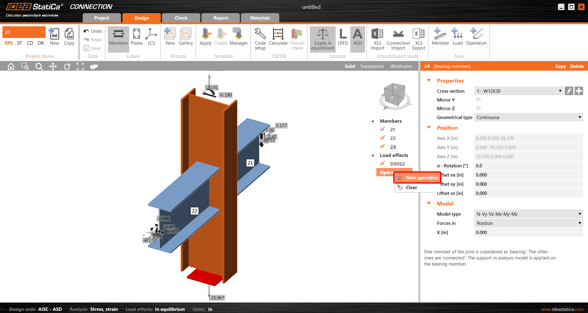
Automatic data transfer is started and IDEA StatiCa Connection with a generated project is launched. All members and load effects were added automatically.
This tutorial works with imperial units. If you use metric units, you can switch them to imperial by clicking on the unit in the bottom part of the window.

Now you will define a set of manufacturing operations to model the connection between members. In the items tree, you right-click on Operations and select the option New operation.
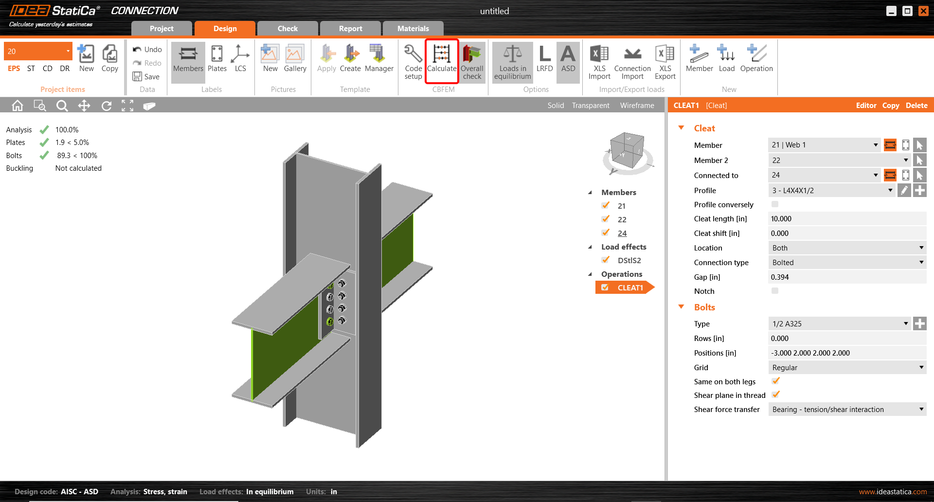
And you add the operation Cleat.


And set the properties of CLEAT1 as follows:

You can check the design of this simple joint.

4 Check
The analysis based on CBFEM is started by the icon Calculate from the top ribbon. The analysis model is automatically generated, the calculation is performed, and you can check the results.
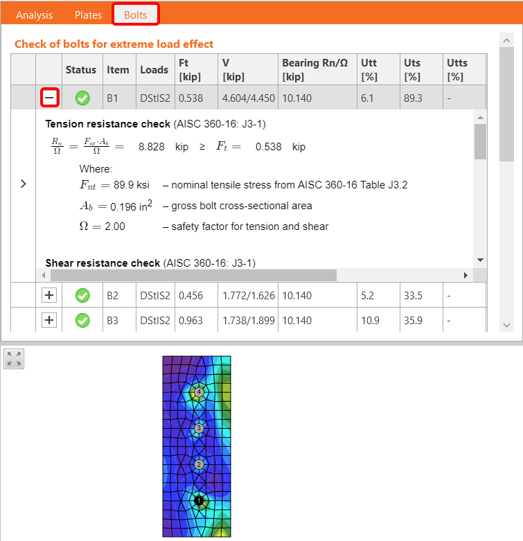
Activate Overall check, Equivalent stress, Mesh and Deformed from the ribbon to get a full picture of what is happening in the joint. Everything is displayed in the 3D window.

All values can be reviewed in detail in the tables and 2D windows. For example, to display the check of bolts, select the Bolts tab.
5 Report
At last, go to the tab Report. IDEA StatiCa offers a fully customizable report to print out or save in an editable format.

You have imported, designed, and code-checked a steel joint according to AISC.
6 Synchronize models
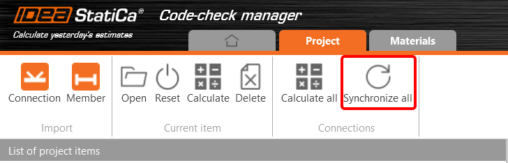
The Code-check manager is a BIM tool to export and synchronize connections from other programs. It is launched directly in the 3rd party applications via a command/icon.
Synchronize all - IDEA StatiCa detects changes in all already imported entities (changes in thickness, changes in cross-section, modification of properties of welds, bolts, etc.) and updates the project in IDEA StatiCa Connection.
Calculate - Synchronize and calculate the current item and provide a new set of results.
Calculate all - Synchronize and calculate all items and provide a new set of results.
Note
Kindly be aware that IDEA StatiCa syncs with a model of the 3rd party application, not the other way around.
Save the project in IDEA StatiCa and close the application Connection. All joints exported from the ETABS project to IDEA StatiCa are kept on the list inside ETABS.
Unlock the model and change the cross-section of member 22 from W12x30 to W12x26.

Run the analysis, select the export command in the upper ribbon, and in the Code-check manager, click on Synchronize.
In the next step, you can Open the joint in IDEA StatiCa Connection to explore the changes.
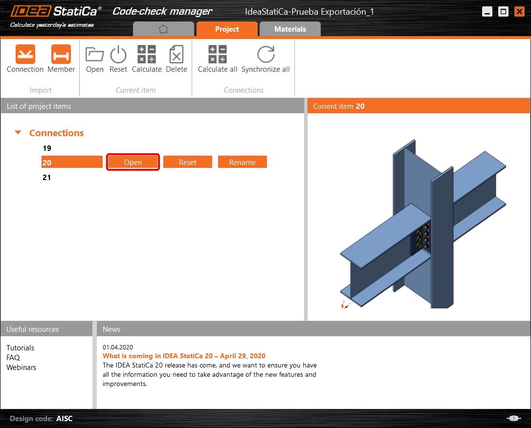
As you can see, the cross-section of the Member 22 has been changed, but all previous operations remained.

You have imported, designed, and code-checked a steel joint according to AISC.
Limitazioni note per ETABS / SAP2000
Il link ora funziona per un'ampia varietà di connessioni/giunti. Tuttavia, si prega di tenere conto delle funzionalità non ancora supportate:
Limitazione: Combinazioni di carico
Non è supportata l'importazione di combinazioni di carico che contengono aggiunte di combinazioni di carico diverse da quelle lineari.
Non è supportato il riferimento di una combinazione di carico all'interno di un'altra combinazione di carico.
Limitazione: Come eseguire i collegamenti SAP2000 ed ETABS con IDEA StatiCa 22.1.
Versioni problematiche:
- SAP2000 24.1.0
- ETABS 20.3.0
Descrizione del problema:
Soluzione:
Questo vale anche per SAP2000 ed ETABS (ultime versioni). La soluzione consiste in:
1. Individuare il file di configurazione ( SAP2000.exe.config o ETABS.exe.config) in
C:\Programmi\Computer e strutture\SAP2000 24\
oppure
C:\File di programma\Computer e Strutture\ETABS 20\
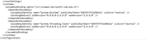
2. Eliminare le seguenti righe dalla parte inferiore del file e salvarlo (richiede i diritti di amministratore).

In alternativa, copiare il file sul desktop, modificarlo e copiarlo nuovamente nella cartella originale.
Ecco come dovrebbe apparire il file (la parte inferiore) dopo che l' assembly binding è stato correttamente cancellato:
3. A questo punto è possibile eseguire il Checkbot.
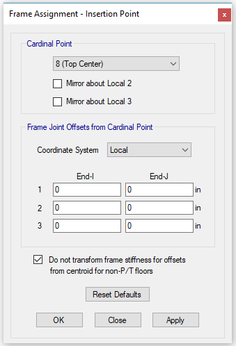
Limitazione: Equilibrio
Per garantire l'equilibrio dei nodi, impostare gli offset di lunghezza finale su 0:


Limitazione: Eccentricità - Il centroide non è impostato come Punto cardinale
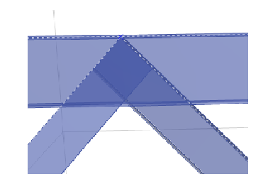

Soluzione: Importare l'intero giunto e spostare manualmente le travi con eccentricità nella posizione corretta.