
Weld sizing - automated tool to design weld size
The Weld sizing tool calculates the optimal weld size based on specific inputs and defined strategies, such as Capacity estimation, Full strength, Minimum ductility, or Overstrength. The new design is created based on the selected settings, which are further explained below. This feature acts as a powerful assistant to eliminate manual iterations, offering a solid design proposal ready for your final verification.
In IDEA StatiCa Connection, there are two strategies of weld sizing available to all users:
- to full-strength
- with over-strength
For Eurocode users, there are two more:
- to capacity estimation
- to minimum ductility
For AISC users, there is one more:
- to capacity estimation
How to call the functions
- Weld sizing can be called by:
Clicking the button Weld sizing in the top panel
In the Operations dialogue
Right-clicking on the Operations by selecting Autodesign all, but here you will autodesign not only welds but also bolts
Right-clicking on the operations and selecting a specific type of Weld sizing
Right-clicking on the operation with weld and selecting Autodesign, but here you will autodesign not only welds but also bolts, in a specific operation

When you call the function, it is necessary to specify the Weld sizing method in the Operations dialogue. Generally, the size of welds will increase in this order:
- To capacity estimation
- To minimum ductility
- Full strength
- With over-strength
The methods are described in detail below.

Settings affecting the weld sizi
The weld sizing process is determined by the specific global settings. The algorithm evaluates the following inputs:
- Welds: Target capacity utilisation: This limit is defined in Project settings > Design – General (Default value is 0.9). The algorithm compares the real acting loads against this set value to find a solution that complies with the requirement.
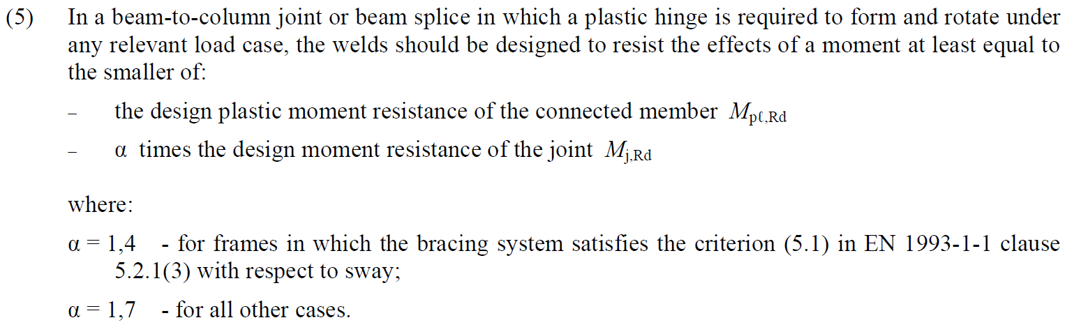
- Welds: Overstrength factor: This factor ensures the weld is stronger than the connected member to allow for plastic hinge formation, as recommended by EN 1993-1-8 – 6.2.3 (5) (typically 1.4 or 1.7). The limit is defined in Project settings > Design – General (default 1.4) and is applied only when the 'Overstrength' sizing method is selected.
- Rounding Rule: The height of a weld is adjusted according to the rounding settings in Project > Preferences > Application units - New entity rounding > Weld size.
- Controller increments: The minimum value by which the algorithm increases the weld height is set in Project > Preferences > Application units - Controller increments> Weld size.
Capacity estimation
Weld sizing to capacity estimation automatically provides weld sizes that are strong just enough to transfer the set loads.
How does the function work
In the results tab for welds, there are two utilisation ratios listed. The Ut (stress utilisation) shows the utilisation value of the most stressed finite element of the whole weld (peak value), while the Utc (weld capacity utilisation) shows the utilisation of the whole weld and thus gives the user information about the remaining weld capacity.
Since stress distribution in welds in FEM-based models varies uncertainly based on the applied load, it is not simple to determine the remaining capacity as a linear function. With an increment of applied load, the change in weld stress distribution can be very dramatic.

The calculation of Utc uses a machine-learning estimation function. Based on learning from a vast number of welded connection models and various load scenarios, the algorithm can accurately predict the remaining weld capacity. The number is displayed in Check, in the Welds tab in the Utc column.
This functionality uses AI and machine learning to determine the capacity of welds. And what's best is that the application can do it within a 10% threshold! This can be considered an excellent result.

At the moment, it is implemented in Eurocode and AISC.
Weld sizing to capacity estimation requires results. The size of fillet welds is adjusted according to the following formula:
\[ a_{new} = a \cdot Ut_c / Ut_{target} \]
where:
- \(a_{new}\) – adjusted fillet weld size
- \(a\) – previously set fillet weld size
- \(Ut_c\) – capacity estimation based on a machine learning algorithm visible at the Weld check
- \(Ut_{target}\) – target utilization in Settings → Design → Autodesign → Weld sizing
Note that weld sizes are limited by detailing rules, e.g., weld size cannot be smaller than 3 mm (EN 1993-1-8 – 4.5.2). These detailing rules are adhered to. Also, keep in mind that multiple welds in IDEA StatiCa are often set to a single value. In these cases, the size is set according to the most utilized one.
Also, a calculation loop is available. When the weld sizing method is set to capacity estimation, it:
- Sizes the fillet welds to full strength
- Calculates the model
- Sizes the fillet welds to capacity estimation
- Calculates the model

Welds are then set at or below the target utilization with just one click.
Minimum ductility
Weld sizing to minimum ductility automatically provides welded connections that are strong enough to prevent brittle failures. The weld strength allows for the initial yielding of the plate, but ultimately, the weld ruptures.
The requirement for minimum ductility of welded joints in FprEN 1993-1-8:2023 – 6.9(4). It originates from the Dutch national annexe of EN 1993-1-8, where the fixed ratio of weld strength to plate strength is 0.8. It is also included in widely-used Green books from the UK, namely in Chapters C2 and C3. However, the fixed ratio is suitable only for steel grade S355. In the second generation Eurocode, this is expanded for all steel grades.
This requirement is checked for double-sided fillet welds by:
\[a/t=\frac{\beta_w\gamma_{M2} f_y}{\sqrt{2} f_u \gamma_{M0} } \cdot \min \left \{1.0, 1.1\frac{f_y}{f_u} \right \}\]
where:
- \(a\) – weld throat thickness
- \(t\) – thickness of the plate connected by the edge
- \(\beta_w\) – weld correlation factor
- \(\gamma_{M2}\) – safety factor for bolts and welds; editable in Code setup
- \(f_y\) – plate yield strength
- \(f_u\) – weld ultimate strength
- \(\gamma_{M0}\) – safety factor for plates; editable in Code setup
The weld throat thickness for a single-sided fillet weld is twice larger than that of a double-sided fillet weld.
Note that the method is useful for transversely loaded welds and works if the plate is connected by its full width.
Full strength
Weld sizing to full strength automatically provides welds that are stronger than the connected plate. In the calculation, it is assumed that the plates are loaded in tension and welds transversely as the worst case for weld strength and ductility. This design is useful to avoid brittle failures of welds for static loading.
This approach is also included in widely-used Green books from the UK, namely in Chapter C1.
This requirement is checked for double-sided fillet welds by:
\[a/t=\frac{\beta_w\gamma_{M2} f_y}{\sqrt{2} f_u \gamma_{M0} }\]
where:
- \(a\) – weld throat thickness
- \(t\) – thickness of the plate connected by the edge
- \(\beta_w\) – weld correlation factor
- \(\gamma_{M2}\) – safety factor for bolts and welds; editable in Code setup
- \(f_y\) – plate yield strength
- \(f_u\) – weld ultimate strength
- \(\gamma_{M0}\) – safety factor for plates; editable in Code setup
Note that the method is useful for transversely loaded welds and works if the plate is connected by its full width.
Overstrength welds
Weld sizing with overstrength automatically provides welds that are much stronger than the connected plate. Overstrength factor is specified in Settings → Design → Autodesign → Weld sizing. The default value of 1.4 is taken from EN 1993-1-8 – 6.2.3 (5) to form a plastic hinge.
In the calculation, it is assumed that the plates are loaded in tension and welds transversely as the worst case for weld strength and ductility. This design is useful to avoid brittle failures of welds for plastic design or cyclic loading. Note that the large weld size automatically does not guarantee high ductility. On the contrary, it may lead to excessive residual stresses and deformations caused by weld shrinkage.
This requirement is checked for double-sided fillet welds by:
\[a/t=\frac{\beta_w\gamma_{M2} f_y}{\sqrt{2} f_u \gamma_{M0} } \cdot f_{overstrength}\]
where:
- \(a\) – weld throat thickness
- \(t\) – thickness of the plate connected by the edge
- \(\beta_w\) – weld correlation factor
- \(\gamma_{M2}\) – safety factor for bolts and welds; editable in Code setup
- \(f_y\) – plate yield strength
- \(f_u\) – weld ultimate strength
- \(\gamma_{M0}\) – safety factor for plates; editable in Code setup
- \(f_{overstrength}\) – overstrength factor specified in Settings → Design → Autodesign → Weld sizing
Note that the method is useful for transversely loaded welds and works if the plate is connected by its full width.