
RFEM/RSTAB BIM link for steel member design (EN) - OLD
1 How to activate the link
- Install the latest version of IDEA StatiCa
- Make sure you are using a supported version of RFEM/RSTAB
- You need to have the COM module installed in RFEM/RSTAB to create the BIM link with IDEA StatiCa.
IDEA StatiCa automatically integrates the BIM link into your CAD/CAE software during its installation. You can check the status and activate more BIM links for other software installed later in the BIM link installer.
Open IDEA StatiCa and navigate to the panel BIM and open the BIM link installer. A notification "Run as administrator" may appear, please confirm with the Yes button.
Select the software to integrate the IDEA StatiCa BIM link, click the Install button and check the status.

Note: RFEM/RSTAB BIM link provides importing only under the Eurocode (EN) standard.
2 How to use the link
First, open the source file RFEM.rf5 from the provided files for download (at the bottom of this tutorial) and open it in RFEM/RSTAB. There navigate to menu Add-on Modules then External Modules and run IDEA Statica Steel (for RFEM6/RSTAB9 use this process).

The Code-check manager opens and you can start the import process. Select one beam or column in the RFEM/RSTAB model and click Member to import it for the analysis in IDEA StatiCa Member under the EN code.

The member is added to the list together with corresponding joints and by selecting it the wireframe model together with the tab of cross-sections is displayed. In this step, you can manage the imported load cases. Leave the default settings and start configuring the connections first.

3 Design
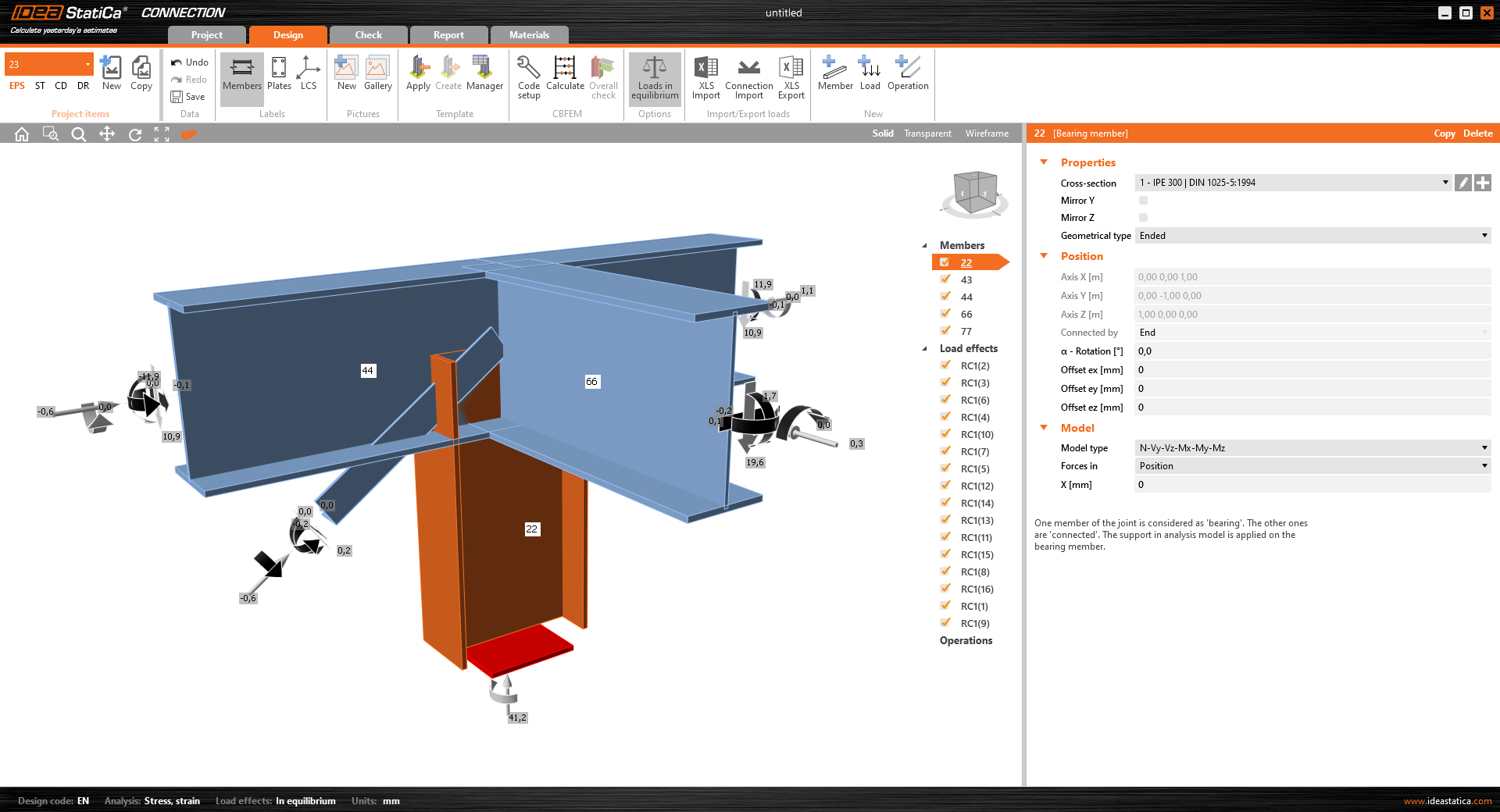
Select node 22 in the list, click Finish, and open it in the Connection module to configure the connections by following the tutorial BIM link tutorial Connection - RFEM/RSTAB (EN) from chapter 3 on.

After that, select node 23, again click Finish, and open it to design the connections.

Instead of designing all the connections of this joint by adding the operations, take advantage of the predefined template from the provided files for download in this tutorial.
Open the template Manager and import the template into your IDEA StatiCa template database.
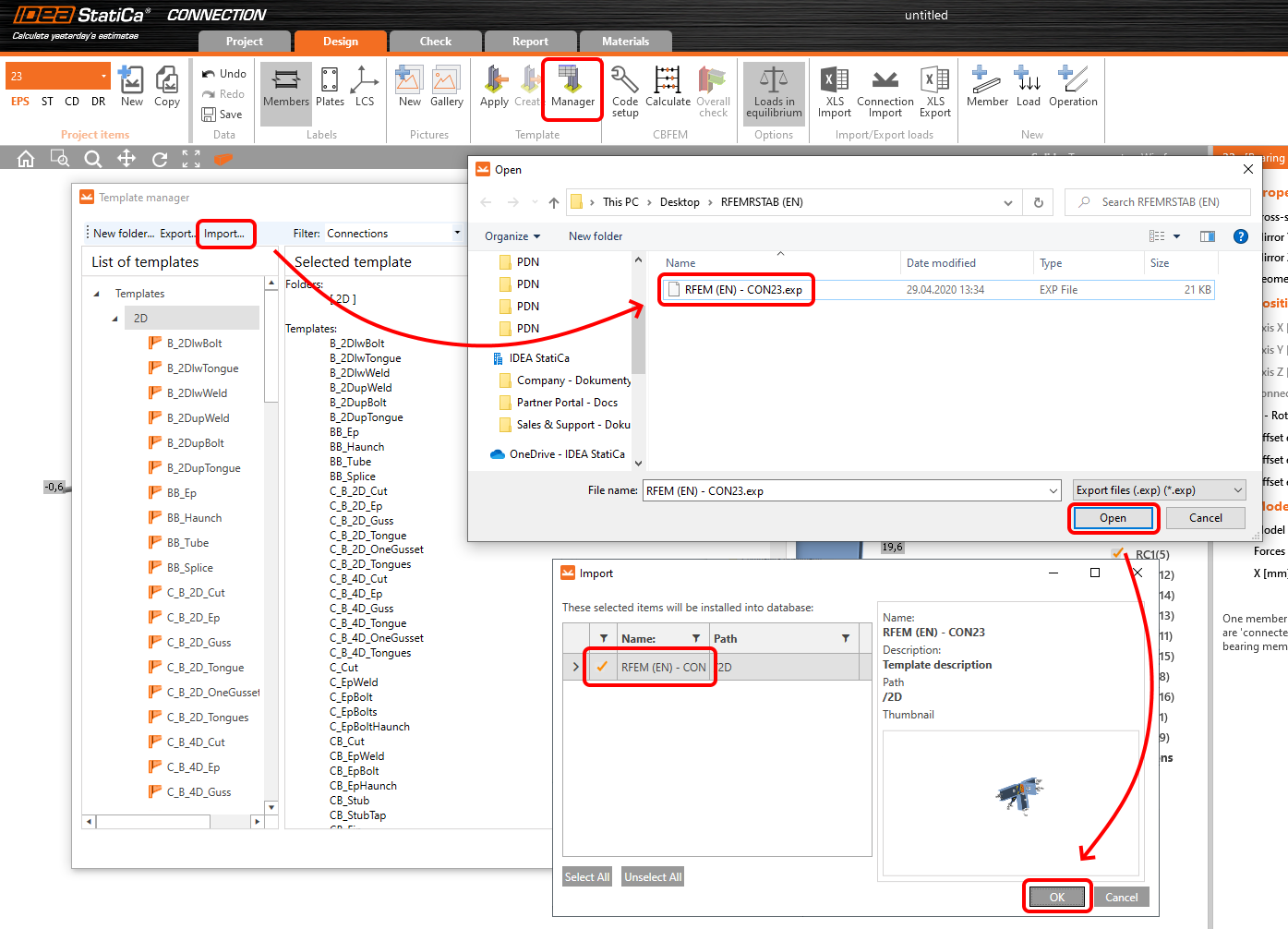
Then click Apply and select the template.

And select the default bolt assembly for this connection item.

The design template is applied and you can just click Save and close the Connection module, or you can run the analysis now and code-check the joint as well.

You have configured and designed both joints that are a part of the analyzed member. Now select the member in the list and click Finish.

And open it in the Member module.

All the data such as geometry and loads have been imported, and all connections have been already designed. The model is ready to be analyzed, but first, let's add some openings to the web of the member. Right-click on Operations in the tree menu and pick the operation Opening.

Edit the parameters of the operation, change the size and shape to N-gon (polygon with n sides) and multiply the openings number.

4 Check
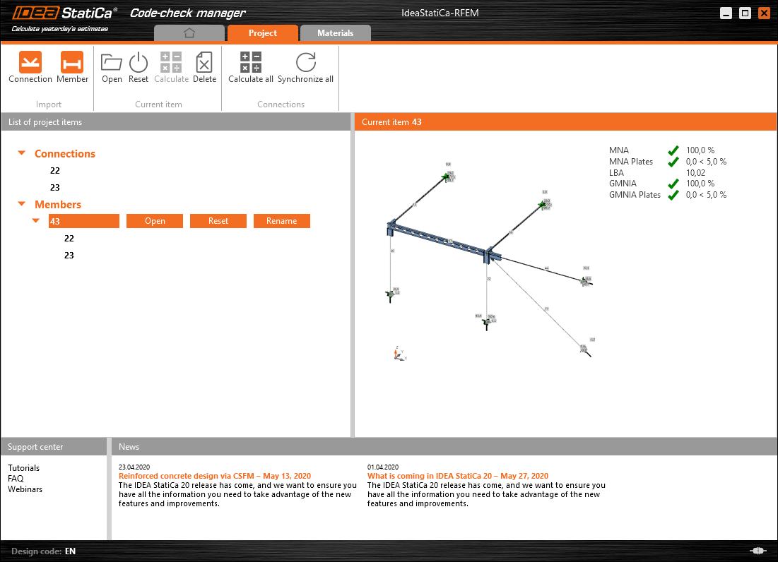
Move to the Check tab, select the MNA (Materially Nonlinear Analysis) and start the analysis by clicking Calculate in the ribbon. The analysis model is automatically generated, the calculation is performed and you can see the overall check displayed together with basic values of check results.

In the next step, switch the CBFEM analysis type to LBA (Linear buckling analysis) and run the analysis again by clicking Calculate.

When the analysis is finished, you can browse the buckling shape factors in the tab, and by selecting some, e.g. buckling shape 1, you can see it visualized in the 3D window. Selecting the Uy results display highlights the deformation trend.

Now you can calculate the GMNIA (geometrically and materially non-linear analysis with imperfections). According to EN 1993-1-1, choose the most critical buckling shape or a combination of buckling shapes and input the initial imperfection of the critical beam. In this case, buckling shape 1 is the most critical one. Switch to the GMNIA tab in the right panel and determine the imperfection of 10 mm (0,5xL/300 = 0,5*6000/300 = 10 mm) to type in as the Amplitude in column 1. Click the Calculate button, for this analysis, the calculation may take several minutes.

The member passed the code-checks with applied initial imperfections and we can browse the results such as stress distribution and internal forces diagram.

5 Report
At last, go to the tab Report. IDEA StatiCa offers a fully customizable report to be printed out or saved in .doc editable format.

You have imported a member from RFEM and designed and code-checked it according to Eurocode (EN).
6 Synchronize models
Save the project in IDEA StatiCa Member and close it. All structural details imported from RFEM/RSTAB project to IDEA StatiCa are kept on the list. The Code-check manager provides useful commands for further processing of the imported items.
To demonstrate the synchronize function, change the cross-section of the analyzed member.

Then, recalculate the project in RFEM/RSTAB and open the Code-check manager again.
Select the member from the list and click Synchronize all.
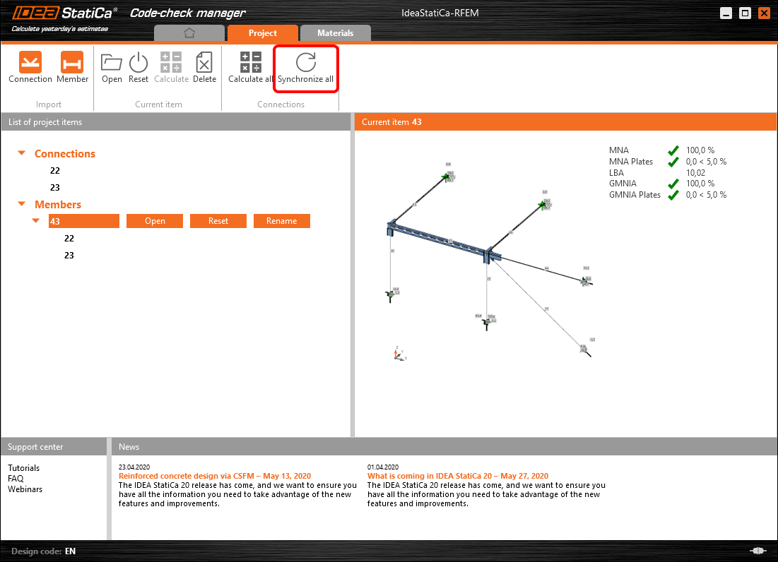
The geometry and load effects were updated and you can click Open to check the project item.

IDEA StatiCa opens and you can see the updated geometry while the design operations keep the settings.

You can check and adjust the design, recalculate and code-check the member, save and close it. Then you can continue importing and code-checking more joints or members.
Known limitations for RFEM/RSTAB
For now, the link works for a wide variety of connections/joints. However, please take into account yet unsupported functionality.
Limitation: Exporting a beam with a haunched end or another type of conical or other shaped beam ends is not possible.
Workaround: The haunch is neglected and can be modelled afterwards in IDEA StatiCa
Limitation: Exporting a connection on a continuous member without an intermediate node doesn't work.
Workaround: Add the intermediate node using the command for members "Divide Member Using n Intermediate Nodes". The option "Place/Create new nodes without dividing it" to keep the member continuous will work only in RFEM 5. The Checkbot application can recognize only "Standard" node type, "On Member" or "On Line" node type will not be recognize.
RFEM 6:

RFEM 5:

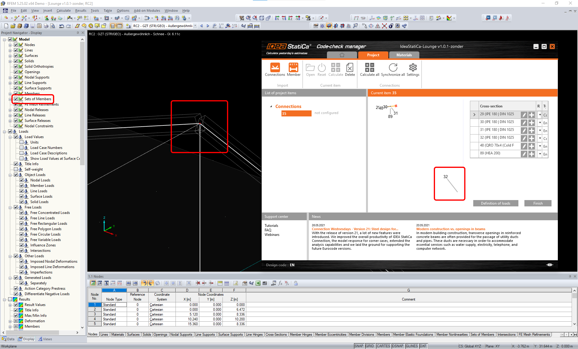
Limitation: Export of a node when the display setting "Sets of member" is turned ON may lead to incorrect data transfer for some member cross-sections and import of extra members or an error message.
Workaround: Turn the "Sets of member" OFF and repeat the export of the node.
Limitation: Geometrical eccentricity – joint node is not in the central point.
Workaround: RFEM/RSTAB offers more ways of input of eccentricities. The eccentricity input using the Local x,y,z coordinates causes difficulties in transforming the data to IDEA StatiCa due to the variety of coordinate system options in RFEM/RSTAB. In case, please use the Global X,Y,Z coordinates eccentricity input instead.

Limitation: The object "Joint" is not supported for the data transfer, and it blocks importing the geometry and loads import of connections to Checkbot.
Workaround: Delete the "Joint" objects, recalculate the model, and import the connections.

Limitation: Import of dynamic load cases and load combinations containing dynamic loads is not supported.
Workaround: Change the definition of the dynamic load cases in RFEM/RSTAB to standard load case with each direction of amplitudes separately or input the internal forces in IDEA StatiCa manually or using the XLS import.

Limitation: Import of non-standard LCS is not supported.
Workaround: Use only supported settings of Local Axes xyz.
See the figure:
- green = supported settings
- red = unsupported settings

Limitation of RFEM5/RSTAB8: Load cases assigned to various load groups for different Result Combinations.
It means that in IDEA StatiCa each load case is assigned to only one load group for all combinations, while in Dlubal a load case can be assigned to a different group in different Result Combinations.
Workaround: For all Result Combinations, always assign load cases to the same load group. Alternatively, you can create exact combinations using "Load Combinations" tool.


Limitation of RFEM5/RSTAB8: The effects of all load cases with the same name (i.e. listed multiple times in the result combination) are added together with the corresponding coefficient in Checkbot. This can lead to doubling of certain load cases (e.g. 1*LC7 +1*LC7=2*LC7) and cancellation of other load cases in combination (e.g. 1*LC9 -1*LC9= 0*LC9)!
Workaround: Do not use the same load cases in the same Result Combination more than once in RFEM or RSTAB. If you want to use the load group in RFEM and RSTAB and assign the same load case to a Result Combination once with positive and once with negative sign, do this differently with 2 independent Result Combinations or Load Combinations.

Limitation: Referencing other Result Combinations in Result Combinations is not supported for import into Checkbot.
Workaround: Add load cases to Result Combination instead of adding other Result Combination.

Limitation: Internal forces are not imported into Checkbot if the corresponding result values are deactivated in the Result Table Manager.
Workaround: Open Results → Result Table Manager and activate the required values. Ensure that the following options are enabled:
- Rows: Member starts, Internal points, Member ends
- Columns: Internal forces, Internal moments
