


Coupling Beams and IDEA StatiCa
Role of coupling beams
Coupling beams are typically added to a structure to improve its lateral force resistance. They bridge two separate, independent items together (like shear walls) to add stiffness to the overall system. They are usually short and thick, similar to deep beams. In concrete buildings, in particular, they are often one of the most critical elements.
Figure 1. Fisher, Andrew W., et al. "Response of Heavily Reinforced High-Strength Concrete Coupling Beams." ACI Structural Journal, vol. 114, no. 6, Nov.-Dec. 2017, pp. 1483+. Gale Academic OneFile, link.gale.com/apps/doc/A558752923/AONE?u=anon~dff1dbd&sid=googleScholar&xid=6f6988a6. Accessed 1 Nov. 2022.
Coupling beams have two roles in most buildings. Firstly, the beam couples two shear walls to increase the moment of resistance. If you have two uncoupled shear walls, the force exerted from the side of one wall would not influence the second wall because they are not connected by beams. This means that the force exerted will affect only one wall, which might cause movement independently of the other one. This significantly decreases the structural integrity of the building. By contrast, by coupling the two, you reduce the stress each wall attracts by distributing the forces from one wall to the other through the beam system. Coupling beams also distribute the lateral force across the length of the second wall, which further spreads the tension along the element and enhances the overall resistance of the structural elements.

Figure 2. Yang Liu, Hai Chen, Zi-Xiong Guo & Hong-Song Hu (2020) Seismic performance of subassemblies with composite wall and replaceable steel coupling beam, Journal of Asian Architecture and Building Engineering, 19:2, 123-137, DOI: 10.1080/13467581.2020.1718679
The second role of a coupling beam is to act as a source of energy dissipation during extreme stress. For example, if there is an earthquake, a building has to be resilient against pressure. To be resilient, a structure cannot be too rigid. Otherwise, if there were an earthquake (for example), that building would break at the wall pier and collapse. By contrast, a slight amount of flexibility under extraordinary pressure means that the structure is much more able to maintain essential structural integrity under pressure.
A coupling beam then both strengthens the design of a building as a whole and is designed to yield first to preserve more vital parts of a building if it experiences extreme stress. By accommodating a building’s motion in beam design, structural engineers make more stable and safe structures.
Coupling beam models
The model can be split according to the energy dissipation mechanism on the low/high coupling ratio. Due to the reinforcement ratio and mainly length/ height ratio, the mechanism of plastic hinges will be developed on the coupling beams. Model (1) has a low coupling ratio and l/h >4 and can be designed according to beam theory, and the plastic hinges will appear at the end of the beam. Model (2,3) has a high coupling ratio with l/h<2, and it leads to different mechanisms of plastic hinges caused by the shear force. The models have been modeled and code-checked in IDEA StatiCa Detail and IDEA StatiCa Member.

Figure 3. Type of coupling beams according to coupling ratio and plastic hinges development
Loads and topology optimization
Shear walls can serve as an effective structural system to resist lateral loads, such as earthquakes or wind, in high-rise buildings. Coupling beams that connect these walls, which behave independently on each floor, can improve the building’s lateral resistance capacity and dissipate energy. The internal forces induced by these dynamic loads are mainly in-plane forces. The principal stresses reveal the most demanding areas of the structure and help understand the correct reinforcement layout. The topology optimization uses the strut and tie method, which is familiar to structural engineers.

Figure 4.1. Internal forces and topology optimization for low coupling ratio

Figure 4.2. Internal forces and topology optimization for high coupling ratio
Plastic hinges mechanism
Plastic hinges are developed based on the coupling ratio. Deep coupling beams with a high coupling ratio develop shear plastic hinges located in the middle of the beam. On the other hand, a beam with a low coupling ratio leverages the low bending stiffness of the beams to create the plastic hinges at the ends of the coupling beams.

Figure 5. Shear and flexural plastic hinges
Singluarities annd Stress
Some blah blah and link
Coupling beams code-check
A code check, according to the code, is the main part of the analysis procedure. Let's investigate what we can get from the results for concrete and hybrid coupling beams by using IDEA StatiCa Detail and IDEA StatiCa Member.
Coupling beams - low coupling ratio
Due to its relatively simple detailing and ease of construction, the conventional RC coupling beam is the most extensively used coupling beam type in building design. In low seismic risk areas, conventional RC coupling beams are sometimes sized wider than the connecting shear walls in flat-slab buildings. However, the conventional RC coupling beam does not provide good energy dissipation capacities under high cyclic shear stresses, and significant 'pinching' phenomena are present in its hysteresis response. Diagonal shear failure and sliding shear failure are not avoidable in this type of coupling beam, even with closely spaced transverse reinforcing detailing.

Figure 8. Principal stress in compression

Figure 9. Stress in reinforcement bars

Figure 10. Anchorage bond stress in the reinforcement

Figure 11. Crack development and direction

Figure 12. Nonlinear deflection
Coupling beams - high coupling ratio
Diagonally-reinforced concrete coupling beams are recognized as the most effective type of reinforcing beam to provide ductile performance with excellent energy dissipation capacity, especially when the span/depth ratio is less than 2. Although diagonally reinforced coupling beams exhibit excellent stiffness and highly ductile energy dissipation capacities, some constructability issues limit their application.

Figure 13. Principal stress in compression

Figure 14. Stress in reinforcement bars

Figure 15. Anchorage bond stress in the reinforcement

Figure 16. Crack development and direction

Figure 17. Nonlinear deflection
Hybrid Coupling Beam
Coupling beams are difficult and time-consuming to repair once damaged after an earthquake. Recently, several researchers have developed various types of replaceable coupling beams which can be repaired for post-earthquake. One primary concern for the replaceable coupling beam is to improve the self-centering capacity to reduce the residual drift of structures.

Figure 18. Model of hybrid coupling beams

Figure 19. Equivalent stress

Figure 20. First linear buckling shape

Figure 21. Second linear buckling shape

Figure 22. GMNIA and deflect shape
Conclusion
Each coupling beam type adopted by the industry has its own benefits and limitations. Still, not one single type of coupling beam is applicable to all cases in building design. The conventional RC coupling beam is often the most feasible and economical coupling beam whenever the beam shear stress is low and the beam is controlled by flexure. When the coupling beam span-to-depth ratios are small, high shear stresses are expected. The limitations of these types of coupling beams and the associated anchorage requirement should be kept in mind to choose an appropriate coupling beam type for specific projects. As always, the designer should consider the preferences of the construction team whenever possible, as many contractors will have varying opinions related to each methodology.
IDEA StatiCa Detail을 선택하는 이유는 무엇인가요?
수년간, 저희는 모든 형태와 하중 조건에 대한 콘크리트 상세의 철근 배치 및 규정 검토를 위한 새로운 방법을 연구해 왔습니다. 2016년, 저희는 세계 최고의 기술 대학 중 하나인 ETH Zurich와 협력하여 IDEA StatiCa Detail을 개발하였습니다. 이는 고유한 솔버, 재료 모델, GUI 및 출력 보고서를 갖춘 콘크리트 설계를 위한 혁신적인 도구입니다.
주요 기능, 소프트웨어 내부 방법론 및 결과 검증에 대해 알아보려면 이 소개 웨비나를 시청하십시오:
IDEA StatiCa Detail은 단부 절단, 개구부, 행잉, 브래킷, 다이어프램, 프레임 접합부 등 모든 유형의 벽체, 보 및 상세(2D)에 대한 철근 배치 및 검토를 수행합니다. 저희는 완전한 보고서 및 자재 목록과 함께 설계 기준에 따른 ULS 및 SLS의 명확한 합격/불합격 규정 검토를 제공합니다. 철근의 가장 효율적인 위치는 자동으로 식별됩니다. 결과는 ETH Zurich에 의해 검증되었습니다.
새로운 CSFM(적합 응력장 방법) 방법이 콘크리트 설계의 판도를 바꿉니다
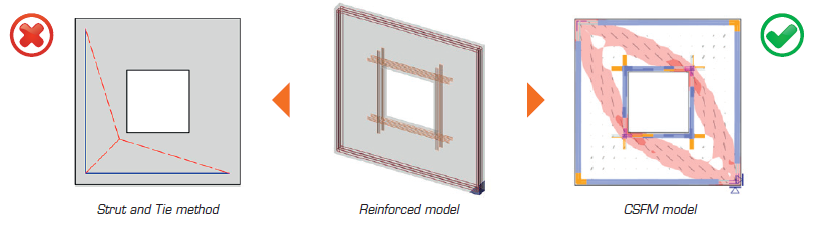
저희는 최고의 기술 대학들과 함께 일반적인 형상과 하중을 가진 콘크리트 상세의 해석 및 검토를 위한 새로운 방법을 개발하였습니다. 이를 적합 응력장 방법(CSFM)이라고 합니다. 수년간의 기초 연구와 이론적 준비 끝에, 애플리케이션의 첫 번째 버전이 개발되어 출시되었습니다.
CSFM(적합 응력장 방법)의 작동 원리
IDEA StatiCa Detail은 유한요소법 해석을 사용하여 표준 설계 접근 방식의 한계를 극복합니다.
- 백그라운드에서 수행되는 비선형 해석.
- 수정 압축장 이론에 의해 결정되는 응력 및 변형률.
- 인장 코드 모델에 기반한 철근 결과.
- 균열 폭 및 처짐 검토.
- 압축 연화.
- 인장 강성 효과.
검증 및 확인
CSFM(적합 응력장 방법) 방법과 IDEA StatiCa Detail의 안전성 및 신뢰성을 확인하기 위해 수행된 모든 테스트 결과는 게시되어 이용 가능합니다. 저희 웹사이트를 방문하여 확인하십시오. Kaufmann 교수와 그의 팀은 또한 CSFM(적합 응력장 방법) 방법을 사용한 구조 콘크리트 설계에 관한 책을 출판하고 있습니다.

IDEA StatiCa Member를 선택하는 이유는 무엇인가요?
최신 애플리케이션인 IDEA StatiCa Member를 사용해 보려고 생각 중이신가요? 어떤 기능을 갖추고 있는지 확실하지 않으신가요?
Member를 소개하는 간단한 프레젠테이션을 확인해 보세요.