
Structural design leveraging the Connection Browser (EN)
1 New project
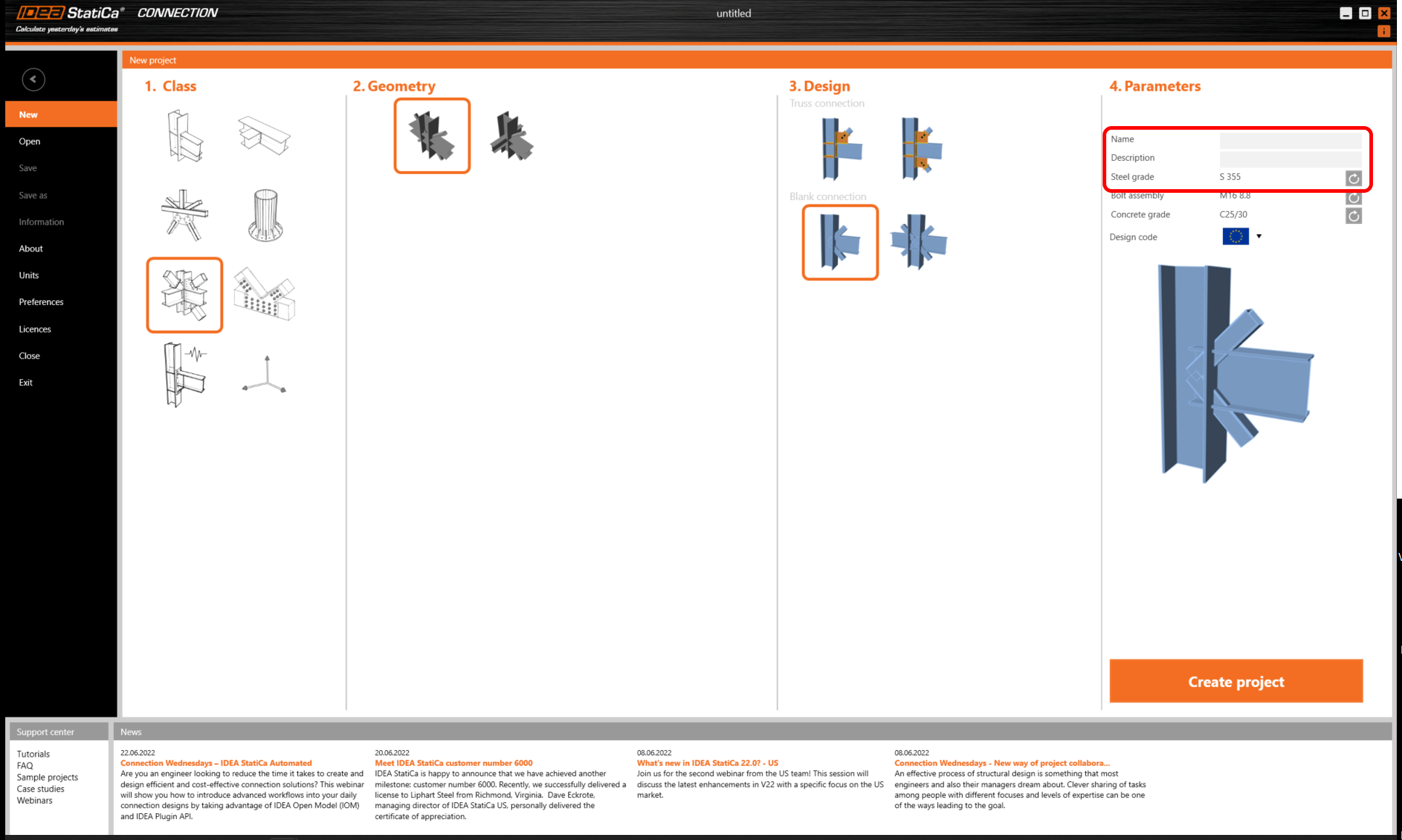
Let’s launch IDEA StatiCa and select application Connection. Create a new project by selecting a starting template closest to the desired design, filling in the name, and choosing the design code and default material properties – S 355.

2 Original operations
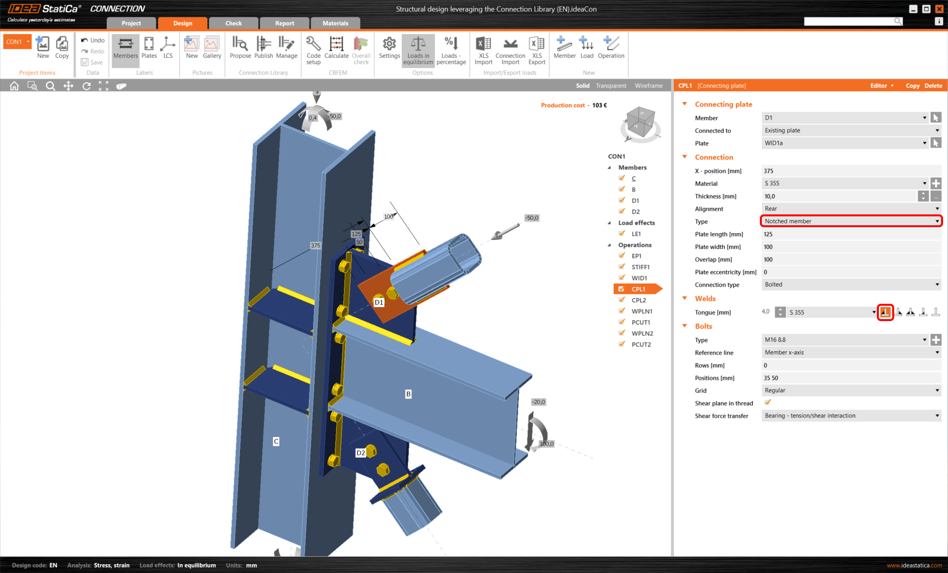
Change the CPL1 operation to 'Notched member' type.
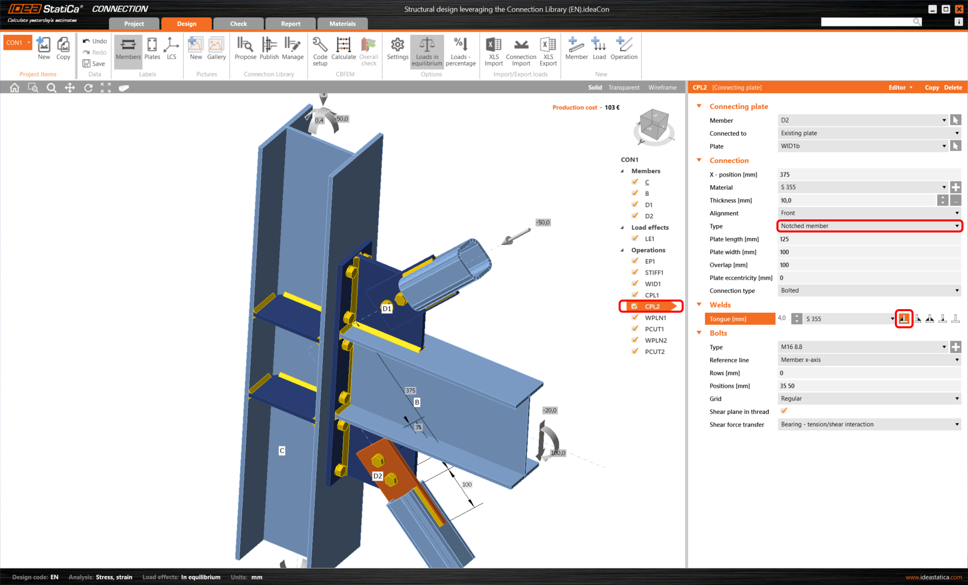
The same change will be applied to the second CPL2 operation.
We will add another set of column stiffeners. Therefore, we just copy the current STIFF1 operation.
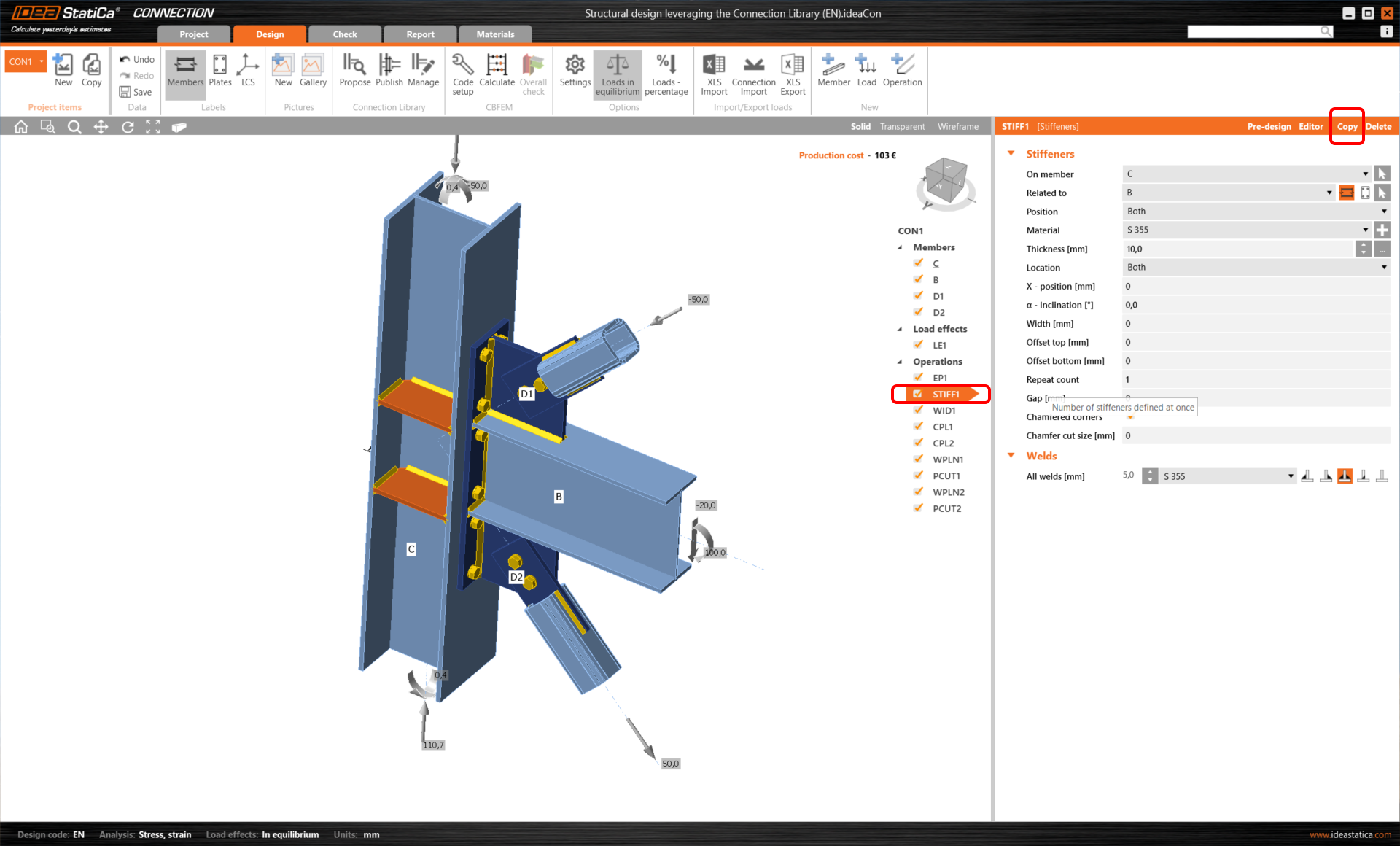
And these stiffeners will be aligned to the edges of the EP1 endplate.

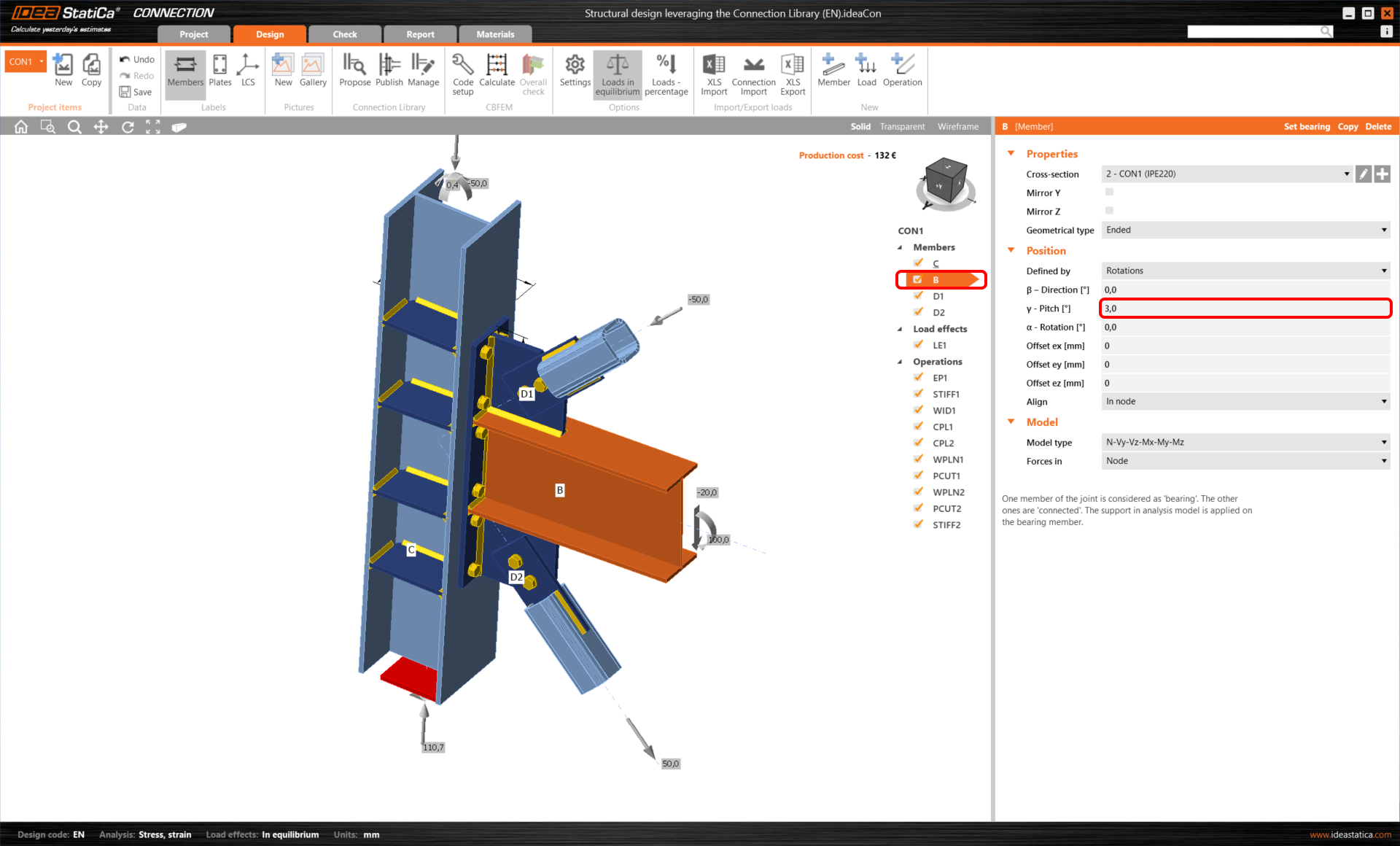
Then we'll change the member B Pitch angle to 3.0°.
3 Connection Browser
Publish your design into to cloud Connection Browser.

Create a new Connection model with this blank wizard template.
Apply your previously saved design from the Connection Browser through the 'Propose' button.

This Design will be applied even when the geometry isn't completely identical. (The B members have a different Pitch angle)
4 Double angle member
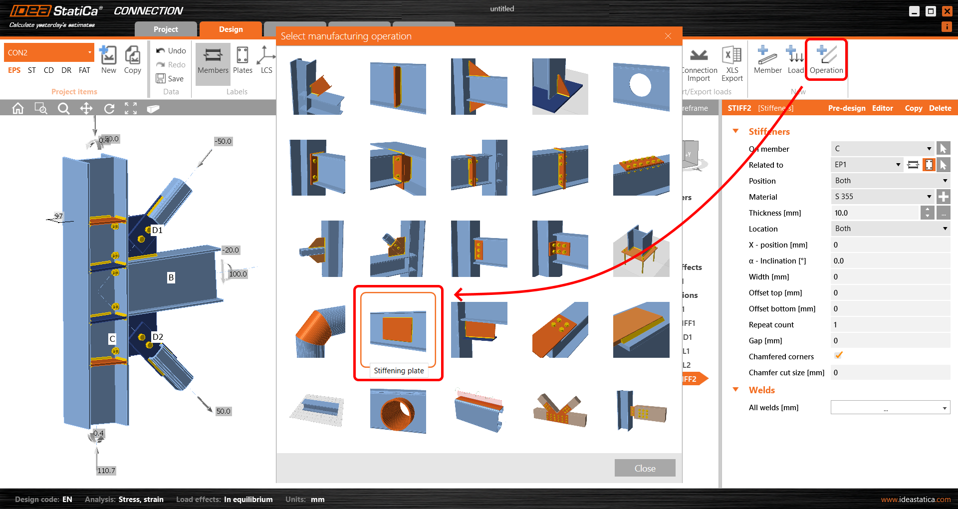
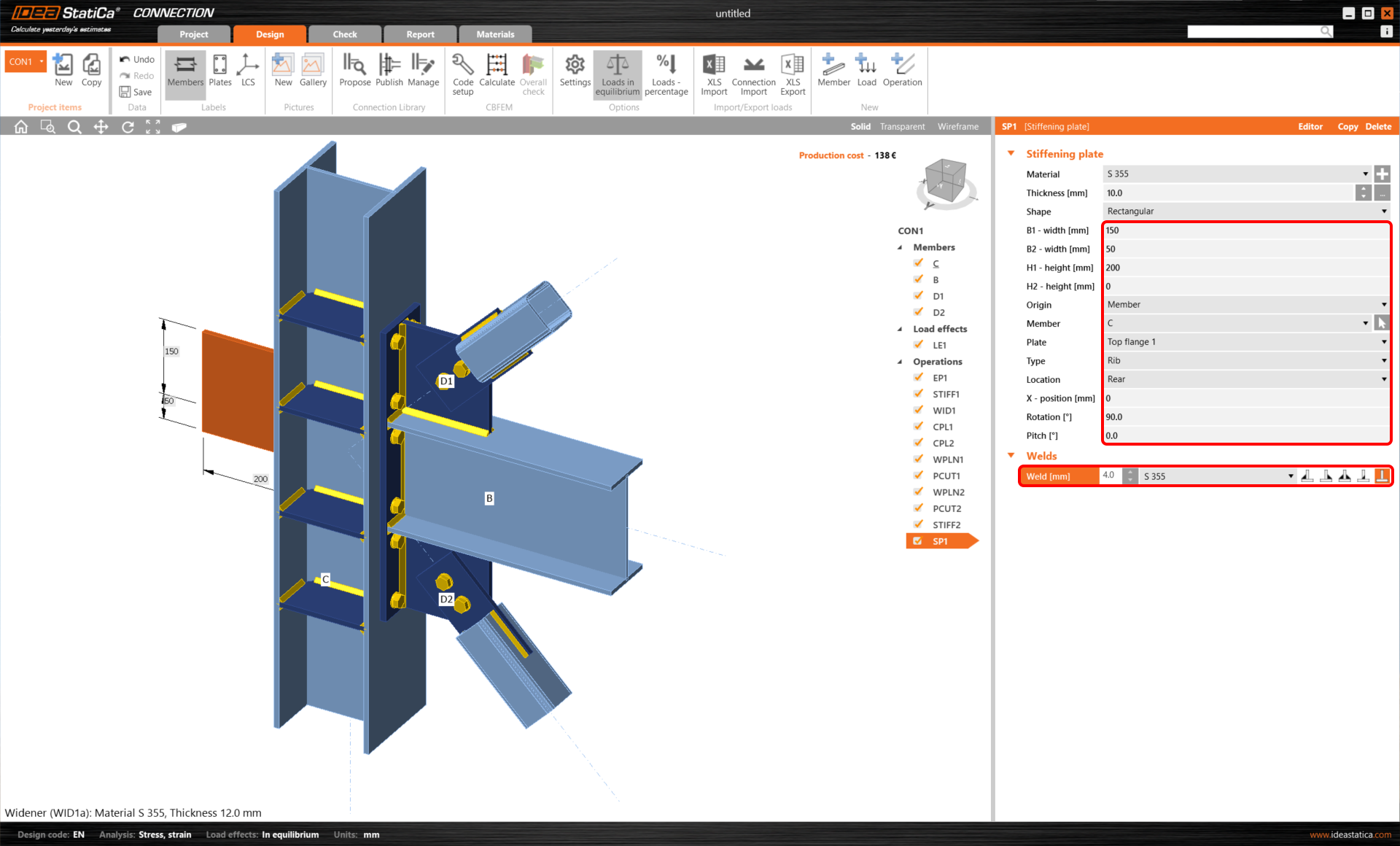
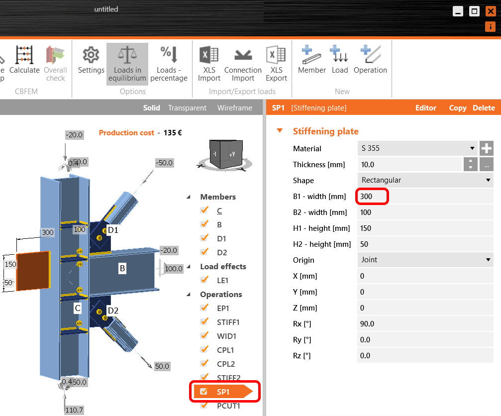
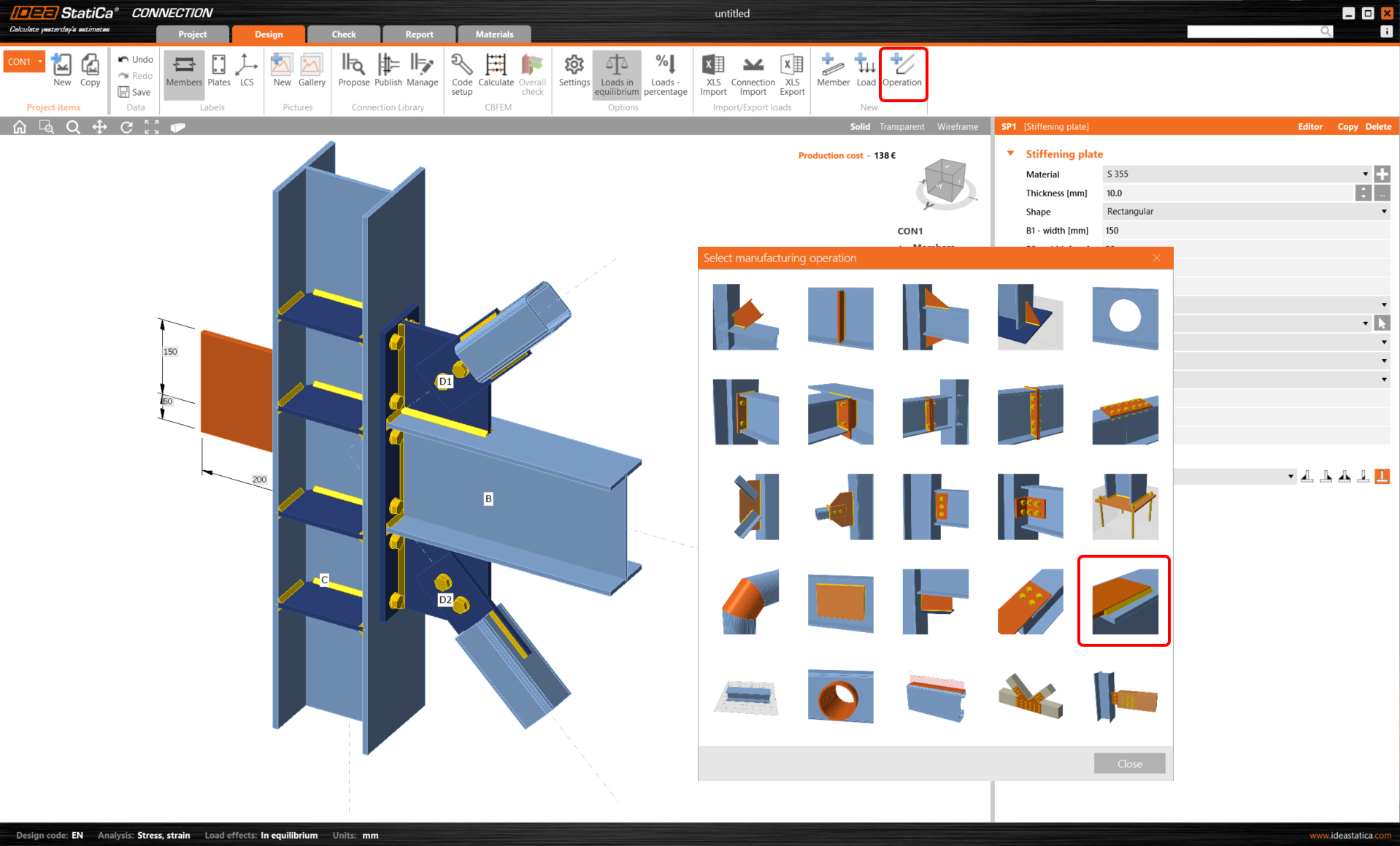
Now we want to use a fin plate connection for a new connected member. So, we will add a Stiffening plate operation for the fin plate.
We change its rotation around the X-axis to 90°.
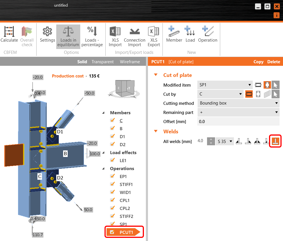
We'll add the Cut of plate operation.
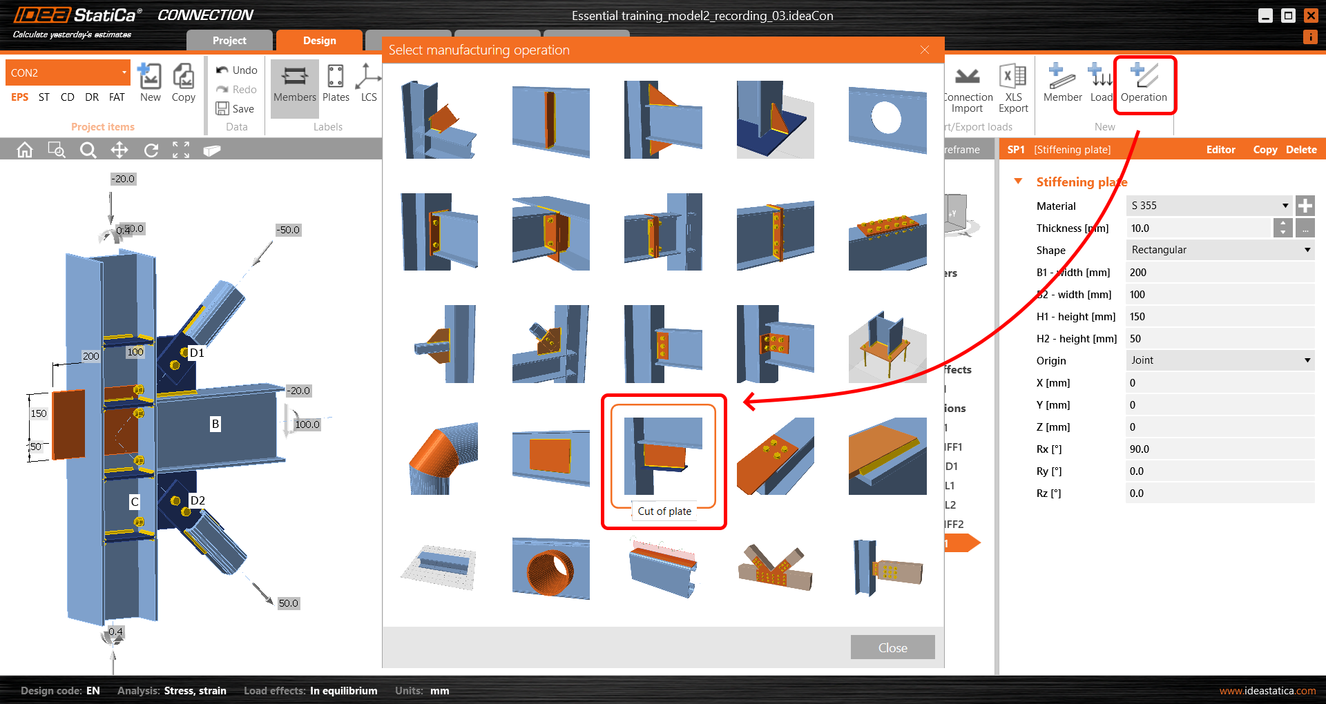
We enlarge the plate to 300 mm in B1 dimension.
Because we want to use an intermittent weld instead of the automatic continuous one, we have to turn the original weld off in the Cut of plate operation.
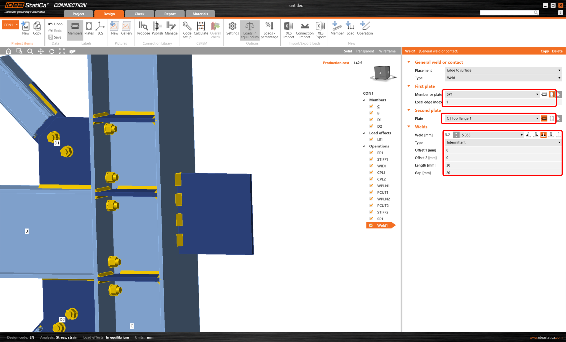
Now we apply a new Weld operation.
And adjust the parameters of the Weld operation for connecting all the correct plates and edges involved.
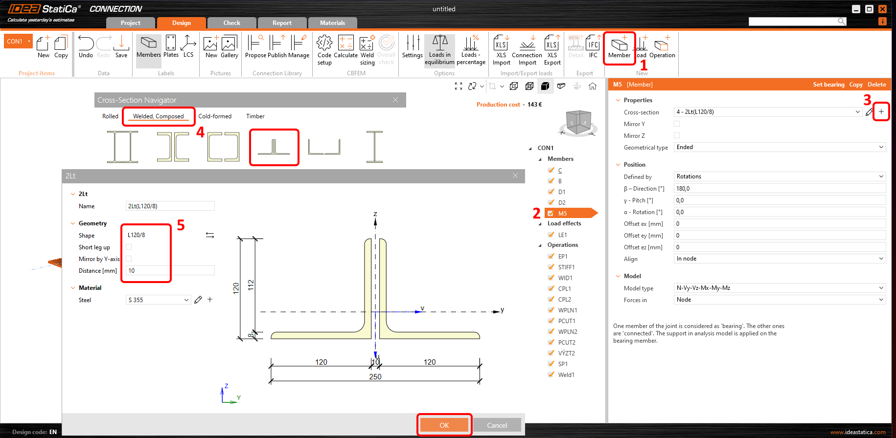
We'll add a new Member M5 with the correct position and cross-section.
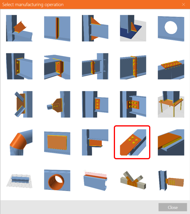
Now, we can connect this new M5 member to the SP1 Stiffening plate with the Bolt grid operation.
The Bolt grid parameters have to be adjusted for the correct values.

Now, you have successfully created a new connection with help of the Connection Browser Propose feature. Furthermore, you have practiced the creation of manual intermittent weld and a bolt grid with 3 plates involved.
