
Release notes IDEA StatiCa 23.1
Version 23.1 highlights
For steel, we did a lot in error-proofing and reporting – welds, load position, and detailing checks. IDEA StatiCa Member now has an input wizard and the ability to select rigid supports, dramatically speeding up your inputs and limiting errors. The fire design of connections also includes calculating the temperatures automatically.
IDEA StatiCa Connection now generates IFC files, including all bolts, welds, and materials. Structural engineers can share connection designs with detailers. Our cloud app, Connection Library, the world's largest online database of steel connections, allows downloading and reusing connection files in the desktop app.
IDEA StatiCa Detail, our solution for the structural design of concrete walls and details, has undergone a complete user interface refactoring. New facelift of icons and ribbon, new modeling commands, better 3D scene, and more reporting options, all of which make your work much faster.
Steel connection design
Export of an IFC file from IDEA StatiCa Connection
One IFC model is more than a dozen drawings
As a detailer, modeling a complex, or even simple, connection design according to 2D drawings provided by a structural engineer can get complicated and create room for error. Therefore, it is important to share as much information between the professions as possible. So, why not use a format that is recognized by every BIM software tool of the industry? An IFC provides you with a 3D representation of the connection, which can be linked to Tekla, Revit, etc., and IFC viewers.
How to export your connection design into IFC
All it takes is one click!
- Design your steel joint in IDEA StatiCa Connection and navigate to the Report tab.
- Click on the IFC export icon, and it's done!

You can export connections into IFC even if you don't use the desktop application!
- Just upload the steel joint to our web application IDEA Statica Viewer.
- Click on the icon of IFC file and IFC of your joint will be automatically downloaded.


The IFC file includes:
- A geometrically accurate model of the connection, including bolts and welds.
- Basic information about cross-sections, bolts, welds, and materials.
- The model defined as an IFC2x3 coordination view

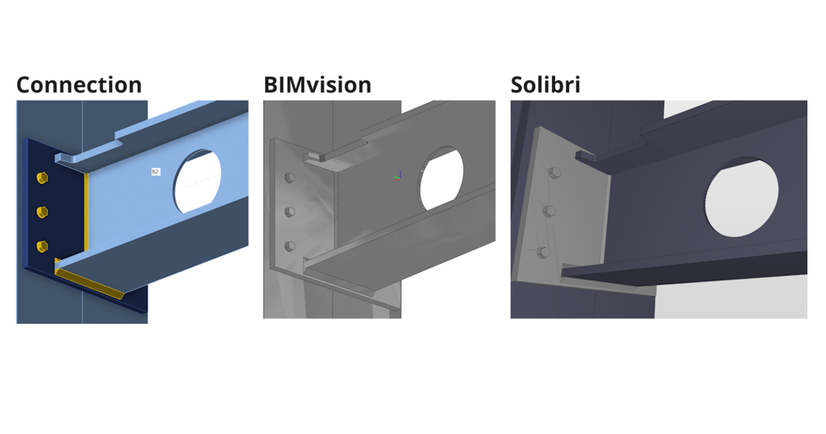
A visual representation of a connection
The IFC file can be imported to BIM/CAD tools (such as Tekla Structures, Autodesk Revit, etc.) as a visual representation of the connection model. This provides the detailer with a better understanding of the model. Opening the model in any IFC viewer software brings you a wholesome view and the possibility to create additional section views, cuts, and measurements.

IFC export improvements (since version 23.1.1)
Here you can find listed improvements and details about the IFC export in 23.1.1 patch:
Supported and verified Viewers:
- BIMvision 2.27.3 and later
- Solibri 9.13.5.12 and later
- Autodesk Viewer (https://viewer.autodesk.com/)
Information about Cross sections and Materials
- Information about cross section and materials are contained in custom properties ("IDEA_CrossSection", "IDEA_MaterialSteel*" property sets).

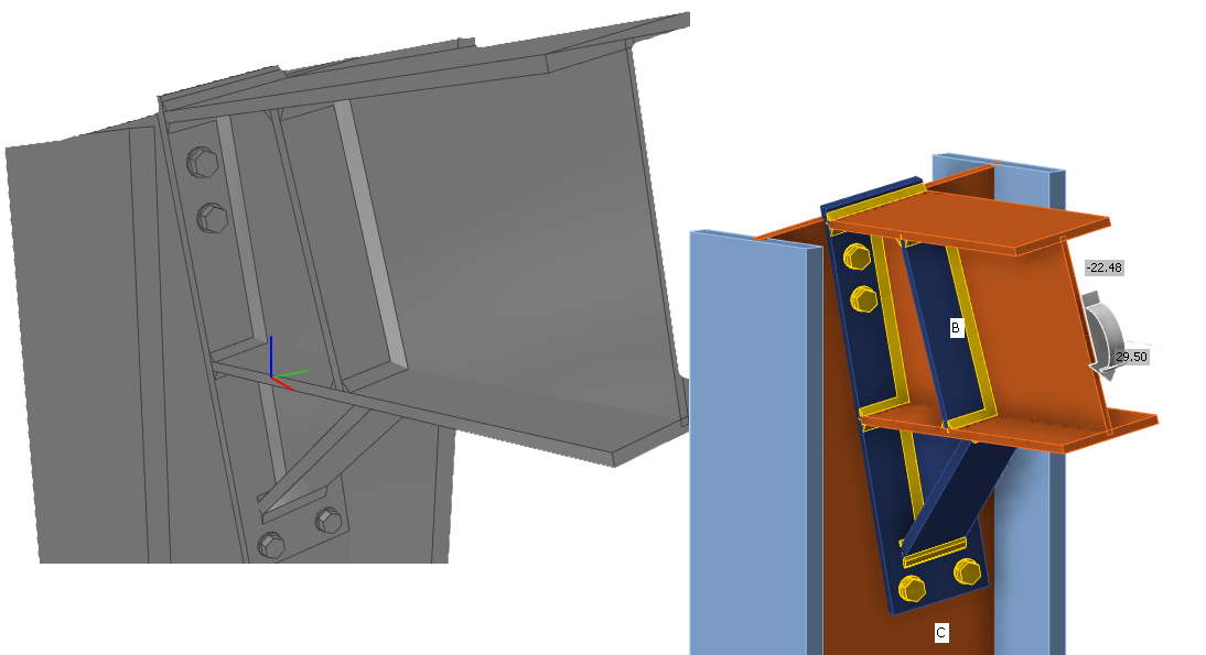
Improved Openings, Notch-cutting
- Notches and Openings operations are supported fully for IFC export and are visualized correctly in IFC viewers (Solibri, BIMvision, and Autodesk viewer checked)
Negative volumes primarily export to IFC
- Negative Volumes with limitations
- In IDEA 23.1.1 added support for "Type" member Limitation - mirroring is not supported (planned for next iteration)
- In IDEA 23.1.1 added support for "Type" plate Limitation - negative plate is exported to IFC and has to be disabled in IFC viewer (planned for next iteration)
Improved bolt positioning during export
Improved IFC export of circular connection plates with unequal meshing
- Circular plates are exported correctly to the IFC
Validated IFC Syntax and Schema of IFC 2x3 by BuildingSmart validation tool
- https://validate.buildingsmart.org/ (note: referencing rules are not satisfied on purpose - referencing welds to multiple edges)
Rods can be exported to IFC from IDEA Statica
- Rods are supported for IFC export
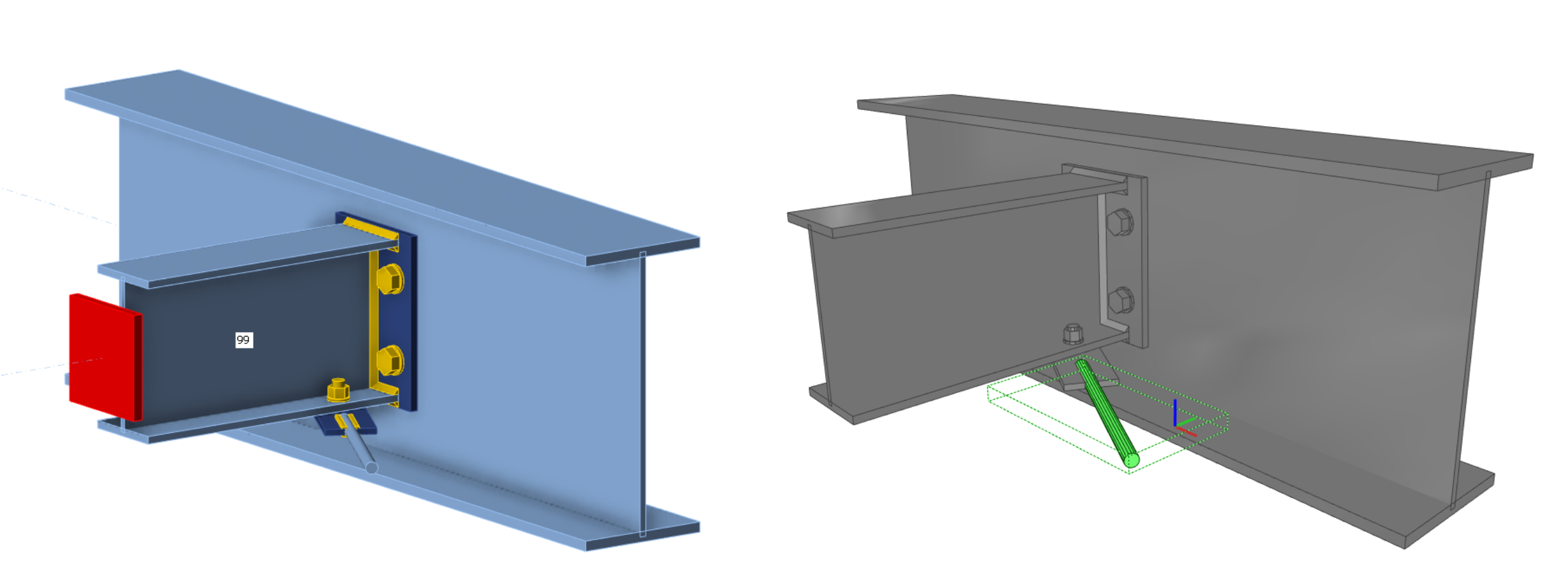
Improved positioning of welds
- Welds are placed on the right edges according to the Connection model
Known limitations
IFC export from IDEA StatiCa Connection app and Viewer is optimized to export 3D geometry with parameters about materials and cross sections of contained objects.
Some software supports importing IFC objects and can even convert IFC objects to native design objects. We want to support this opportunity as much as possible but can’t optimize it for all.
Here, you can see the status of optimization for the following software:
Tekla Structures 2022, 2023
- IDEA IFC model can be imported
- Items can be converted to native objects “as item”
Autodesk Revit 2023, 2024
- IDEA IFC model can be imported as a linked project
Advance Steel 2023, 2024
- IDEA IFC can not be imported into Advance Steel (boundary representation geometry is not supported in Advance Steel)
IFC version
IFC 2x3 as coordination view is exported. (no option for settings)
Beams and plates
Beam and plates are exported as mashed geometry, so they do not act like a dimension object. (Advance Steel import limitation)
Bolt holes
Bolt holes are exported, but not all viewers and tools support viewing them.
Properties
Exported properties are SI units only.
Fire design – automatic temperature calculation (23.1)
Enhanced fire resistance calculations
We have enhanced the functionality released in version 22.1.
Using this method, the temperature in each plate is calculated separately. Fire is assumed to impact the whole connection model and all its surfaces at once. The temperatures of bolts and welds are safely assumed to be the same as the hottest connected plate.

Fire curve, resistance class, material degradation curves, and fire protection properties are set in the app Connection in Settings. Fire protection can be added uniformly to the whole joint.

Available in IDEA StatiCa Steel and IDEA StatiCa Complete editions.
Essayez les nouvelles fonctions d'IDEA StatiCa aujourd'hui
Welds – autodesign, input, warnings, visualization
This article contains outdated information. Please refer to the updated version.
User-defined welding electrodes
Weld material is an editable item in the MPRL (Material and Product Range Library). This means you can define the welding electrodes independently on a steel grade of connected plates.
To add a user-defined welding material, go to the tab Materials, add a Weld material, and Edit its properties.

Also, the correlation factor βw can be modified from the default value of 0.8 to match with values for, e.g., stainless steel requirements (βw = 1.0 for steel weld strength lower than 360 MPa).
You can then assign the welding electrode material in a combo box of any weld of any operation. Alternatively, you can add a new weld material.

Check tables and the report are expanded to always contain information about the welding electrodes and their parameters.
Autodesign of welds to full-strength
This feature allows users to optimize the weld size based on the welded plate strength. This shortens the design time and ensures safe weld size for all welds in the connection project.
You can run the Autodesign weld to full-strength algorithm for all welds within the connection project at once via the right mouse button on Operations in the tree menu.

For the algorithm, the assumptions are that the plate is loaded in tension (more dangerous for weld designs) and the weld length is the same as the connected plate edge length. Plate strength in tension is taken as the weld strength perpendicularly loaded, and the weld size is then derived. The inputs are:
- Thickness of the connected plate by edge (or the thinner plate in edge-to-edge case)
- Yield strength of connected plate material
- Ultimate strength of weld material
- Other weld parameters (factors, coefficients, e.g., βw)
- Partial safety factors for plate material
- Partial safety factors for weld material
Weld throat thickness or leg size value rounding can be set in Settings, Pre-design, and Weld size.

Estimation of a weld's overall capacity
In the results tab for welds, there are two utilization ratios listed. The Ut (stress utilization) shows the utilization value of the most stressed finite element of the whole weld (peak value), while the Utc (weld capacity utilization) shows the utilization of the whole weld and thus gives the user information about the remaining weld capacity.
Since stress distribution in welds in FEM-based models varies uncertainly based on the applied load, it is not simple to determine the remaining capacity as a linear function. With an increment of applied load, the change in weld stress distribution can be very dramatic.
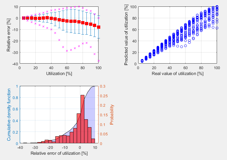
The calculation of Utc uses a machine-learning estimation function. Based on learning from a vast number of welded connection models and various load scenarios, the algorithm can accurately predict the remaining weld capacity. The number is displayed in Check, in the Welds tab in the Utc column.
This functionality is the first successful use of AI and machine learning to determine the capacity of welds. And what's best is that the application can do it within a 10% threshold! Which can be considered an excellent result.

This feature is limited to projects in Eurocode.
General weld highlighted in the 3D scene
There is a simple improvement in the 3D scene of the Connection app for better orientation, especially in bigger connection models imported via BIM links from CAD applications.
When a General weld or contact operation is selected, the weld in the 3D scene is highlighted in orange (by default).

Warning for electrodes stronger than plates
When the Detailing check is activated in the Code setup of the Connection app, users get a warning if a welding electrode material is stronger than the welded plates. This helps to ensure design safety standards.
This applies to Eurocode (EN) and Indian standard (IS), which contain clauses defining that weld strength is determined by the smaller ultimate strength of connected plates and requirements that the added material of welding electrodes must be stronger than the parent material (EN 1993-1-8 – 4.5.3.2 and IS 800:2007 - 10.5.7.1.1).

Butt weld FEM model improvement
The finite element model of butt welds has been updated. The model of butt welds is now similar to the model of fillet welds, which makes it easier for the automatic entity generator to create a butt weld generation under certain conditions, especially for hollow sections.
Improved weld check visualization
Weld checking using a finite element method differs from traditional design calculations. In traditional calculations, small eccentricities, deformations, torsions, and Poisson coefficients, etc., may be neglected.
Stress components are now shown:
- σꓕ
- τꓕ
- τ‖
These stresses are used in all codes for further weld evaluation.

Equivalent stress is colored grey/green/orange/red according to Warning and Optimal check level (editable in Code setup) for higher clarity.

This improved functionality helps engineers understand the stresses in welded connections.
Available in IDEA StatiCa Steel and IDEA StatiCa Complete editions.
Essayez les nouvelles fonctions d'IDEA StatiCa aujourd'hui
The coherent icons and ribbon of IDEA StatiCa Connection
As trends evolve, we ensure the visual style of our applications meet user needs. In IDEA StatiCa Connection, the icons were designed to clearly represent their function, to look coherent, and to navigate easily while working in the application.

A set of icons has been designed specifically for each workflow tab (Design, Check, Report, Materials).
Available in IDEA StatiCa Steel and IDEA StatiCa Complete editions.
Essayez les nouvelles fonctions d'IDEA StatiCa aujourd'hui
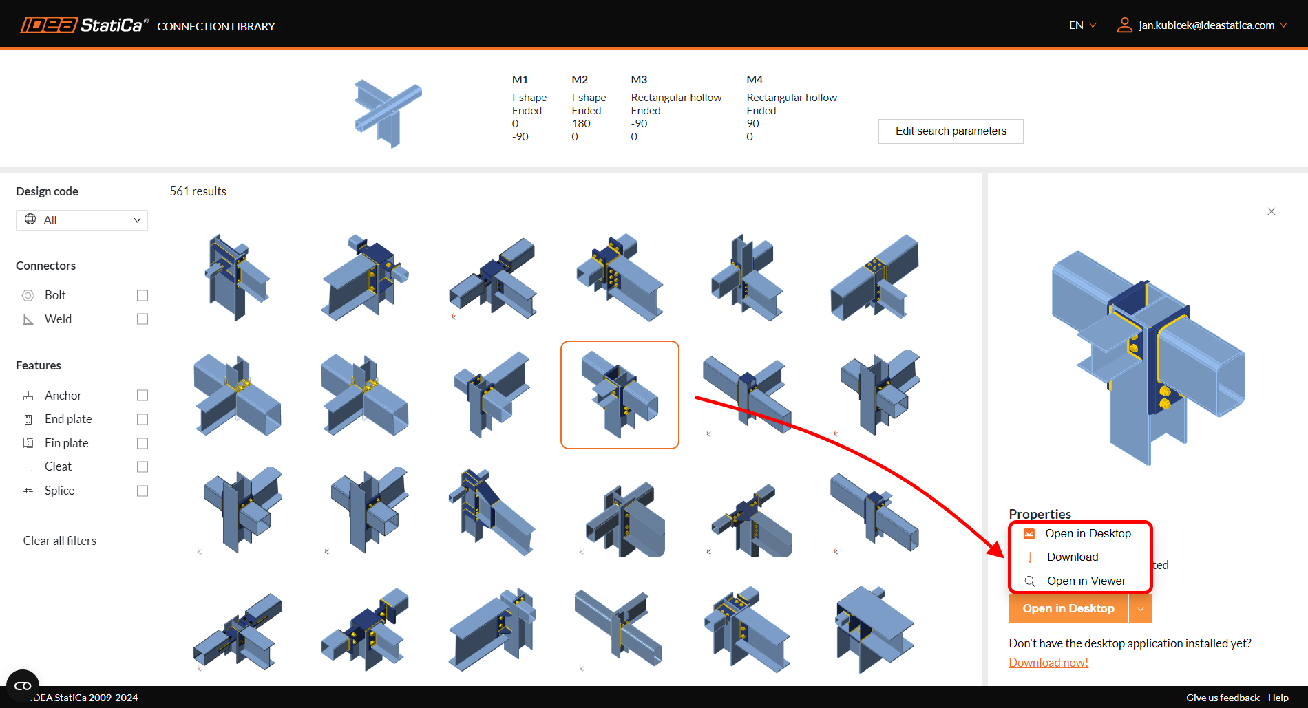
Connection Library - la plus grande base de données d'assemblages en acier téléchargeables
Désormais, vous saurez où trouver l'inspiration. Il vous suffit d'entrer connectionlibrary.ideastatica.com dans votre navigateur Internet.
Grâce à Connection Library vous pouvez parcourir des exemples avec la géométrie souhaitée et trouver l'inspiration en quelques secondes ! L'utilisation de l'application est simple et intuitive ! Le jeu de base de la base de données comprend plus de 1 000 000 de conceptions et s'enrichit chaque jour.
Fonctionnement de l'application
Connection Library est une application web qui permet aux utilisateurs de trouver l'inspiration en leur fournissant une base de données publique de milliers d'assemblages disponibles. Les utilisateurs peuvent ensuite utiliser les assemblages fournis dans l'application Connection ou partager les résultats de la recherche avec d'autres, ainsi que télécharger les assemblages et les utiliser comme point de départ de leurs projets.
L'application se compose de deux pages : la page d'entrée et la page de résultats :
- Sur la page d'entrée l'utilisateur peut définir l'assemblage qu'il recherche à l'aide des paramètres d'entrée disponibles. Une scène en 3D est disponible, ce qui permet de voir clairement à quoi ressemble l'entrée de la recherche.
- Tandis que sur la page de résultats l'utilisateur a accès à tous les résultats correspondant à l'entrée qu'il a saisie précédemment. Il peut examiner les résultats de la recherche plus en détail, utiliser des filtres pour affiner la recherche ou revenir à la page d'entrée et modifier l'entrée.
L'utilisateur peut accéder aux détails d'un assemblage sur la page de résultats après s'être connecté. Si l'utilisateur n'a pas encore de compte, il est possible de s'inscrire. Dans ce cas, l'utilisateur est redirigé vers une page où il peut s'inscrire et obtenir un compte de licence de base. Dans le détail de l'assemblage, l'utilisateur a la possibilité de télécharger une licence d'essai.
La conception sélectionnée peut alors être utilisée ultérieurement :
- Ouvrez directement dans l'application de bureau
- Téléchargez au format .ideacon
- Ouvrez dans Viewer
Les sources de cette base de données sont les modèles d'assemblage créés et partagés par les utilisateurs dans une autre application web - IDEA StatiCa Viewer.
Vous pouvez en savoir plus sur l'utilisation et les avantages de la base de données cloud Connection Library dans cet article de blog dédié à Comment s'inspirer lors de la conception d'un assemblage en acier.
Disponible dans IDEA StatiCa version 23.1 et version 24.1.
Sauvegardez votre modèle préféré
Après vous être connecté, vous pouvez sauvegarder vos conceptions favorites grâce au bouton « signet ». Cela permet de les sauvegarder dans un ensemble privé accessible dans le menu déroulant.

L'aperçu contient également le nombre total de signets, indiquant combien de fois la conception a été sauvegardé par des utilisateurs uniques.

Mise à jour dans IDEA StatiCa version 25.1.
Essayez les nouvelles fonctions d'IDEA StatiCa aujourd'hui
Shear force position input and visualization
An option for setting the shear force position in a connection has been implemented to ensure smoother modeling. On top of that, you can see the bending moment diagram due to unit shear force immediately!
Let's have a look at the features one by one.
Shear force position at the member face
In many cases, the shear force position is assumed at the member face. You can face this situation when designing a connection with, e.g., a cleat, a short end plate, a flexible support, etc. We have developed a way of inputting the shear force position so you can become more efficient and get rid of tedious, repetitive work.
You can set the position using the Connected member face functionality. The software will set it automatically according to the connected member's surface. That means no more manual adjusting using coordinates. And with the change of cross-sections, the position is still kept.

How does it work? Simply select the member for which you want to set the force position, and select the Connected member face option in the Forces in section under Model in the property tab. It is recommended to always select the connected member manually.

The method and position are also shown in the report.

A better way of shear force position visualization
The Connection application now shows you the value of the bending moment from the unit shear force Vz=-1 for every modeled connection. The unit is according to the unit setting (e.g., Vz= -1 kN or -1 kip). The bending moment also respects the unit settings (e.g., kNm or kip-ft).
The diagram can be shown in Transparent or Wireframe visualization mode, i.e., select the member for which you want to see the diagram, and use one of these modes.

The real moment diagram using the load effects input is still shown in the Load effects section.

Available in IDEA StatiCa Steel and IDEA StatiCa Complete editions.
Essayez les nouvelles fonctions d'IDEA StatiCa aujourd'hui
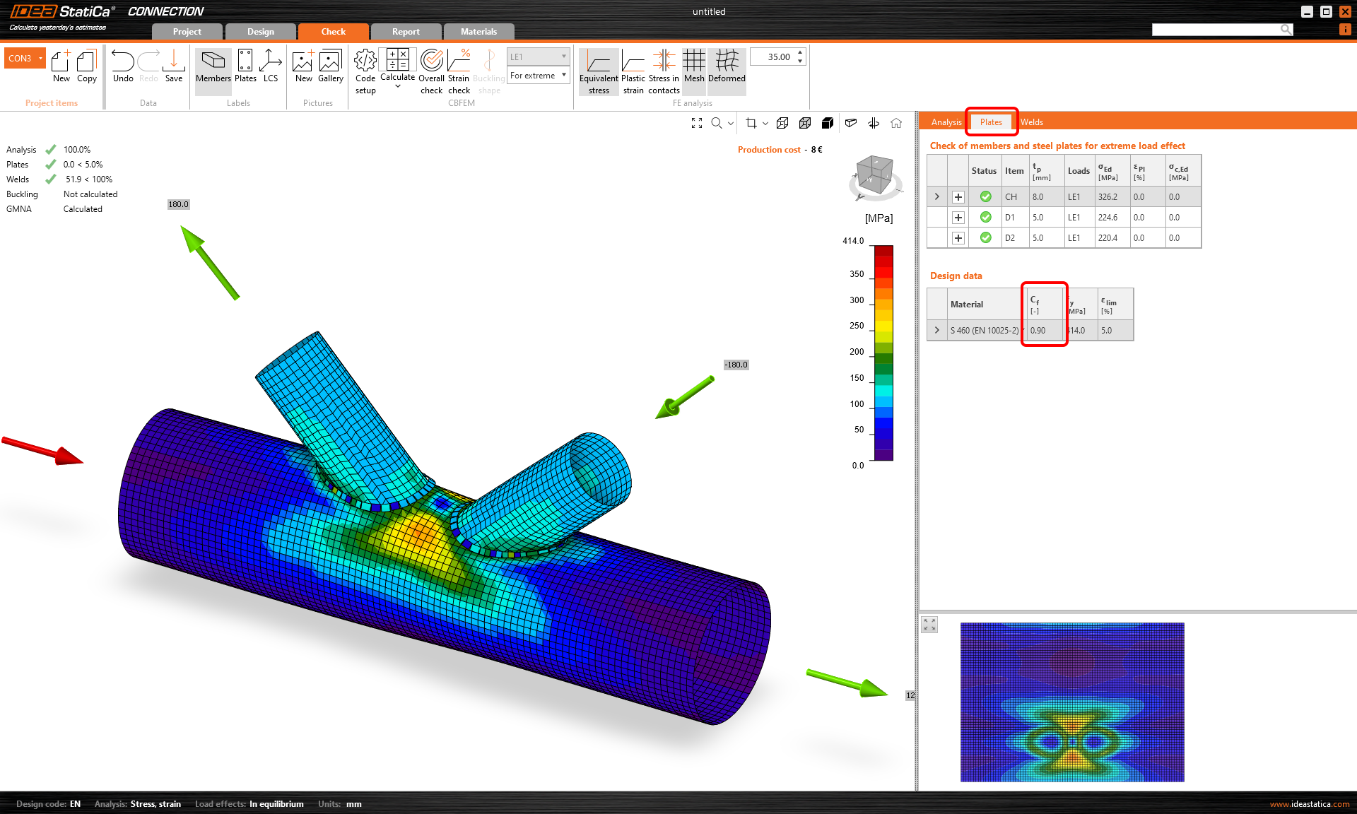
Yield strength reduction for high-strength steel hollow sections
High-strength steel is more brittle than mild steel. The resistance of failure modes of hollow section joints is supposed to be reduced for high-strength steel by a corresponding factor according to EN 1993-1-8, Cl. 7.1.1 (4). Moreover, the same is mentioned in prEN 1993-1-8:2023 – Table 9.1, which is the next generation of design code.
In IDEA StatiCa, the resistance of hollow section joints is determined by the 5% plastic strain of plates. Reliable reduction may be achieved by decreasing the yield strength of steel accordingly.
The yield strength of hollow section joints made of CHS or RHS with high-strength steel is automatically reduced by the reducing factor from the code. This ensures unintentional neglect of the reduction, which might lead to unsafe design.
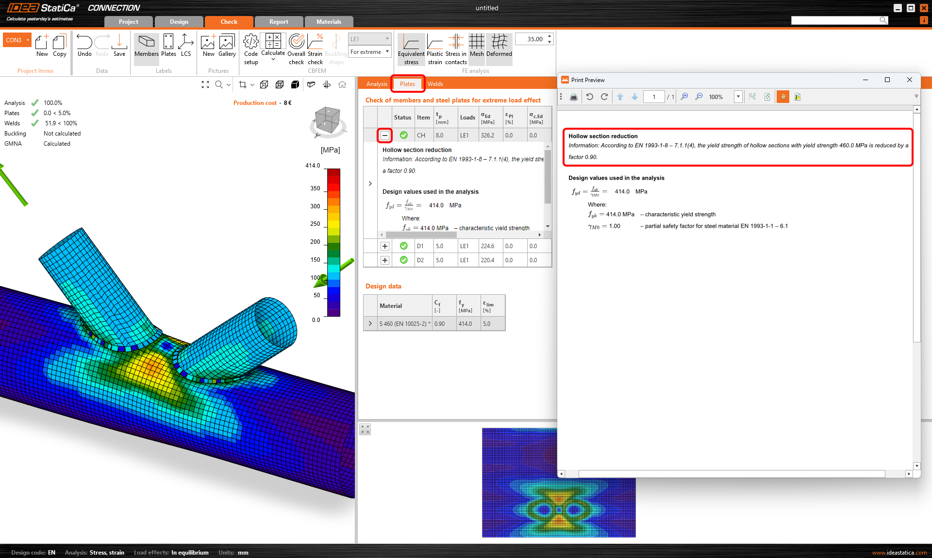
The value of the reduction factor is displayed in the Design data table in the Check section, and in the plates check description.
Available in IDEA StatiCa Steel and IDEA StatiCa Complete editions.
Essayez les nouvelles fonctions d'IDEA StatiCa aujourd'hui
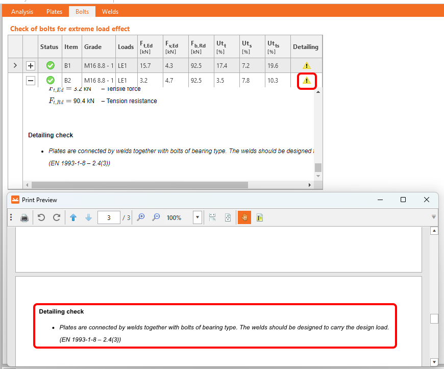
Warnings for welds and bolts connecting the same plates
The detailing check for bolts and welds in the IDEA StatiCa Connection application has been extended by new rules according to all available codes together with references for Eurocode.
Two potential situations for which you receive a warning message in the Detailing check are distinguished:
- The same two plates are connected by both bolts and welds.
- The same two plates are connected by both bolts and preloaded bolts.
1. Bearing bolts and welds
If the same two plates are connected by bolts with shear force transfer set as Bearing – tension/shear interaction and welds, a detailing warning message displays in the Bolts check section.
2. Bearing bolts and preloaded bolts
If the same two plates are connected by bolts with shear force transfer set as Bearing – tension/shear interaction and bolts with shear force transfer set as Friction (preloaded bolts), a detailing warning message displays in the Preloaded bolts check section.

Why pay attention?
Using the above-mentioned approaches in your projects might affect the connection.
The warning message provides you with recommendations. Raised attention to the design is advised but not unconditionally necessary. In other words, the connection won't fail because of the issue, however, you risk an incorrect design.
Moreover, such workflows are not allowed by codes.
Available in IDEA StatiCa Steel and IDEA StatiCa Complete editions.
Essayez les nouvelles fonctions d'IDEA StatiCa aujourd'hui
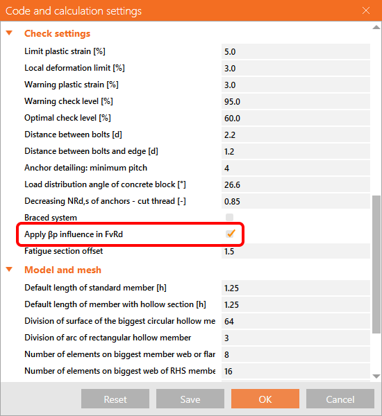
Filler plate (packing plate) recognition
When a filler plate (packing plate) is designed in a bolted connection, the reduction factor βp for the Shear resistance check should be applied using a new algorithm for filler plate recognition.
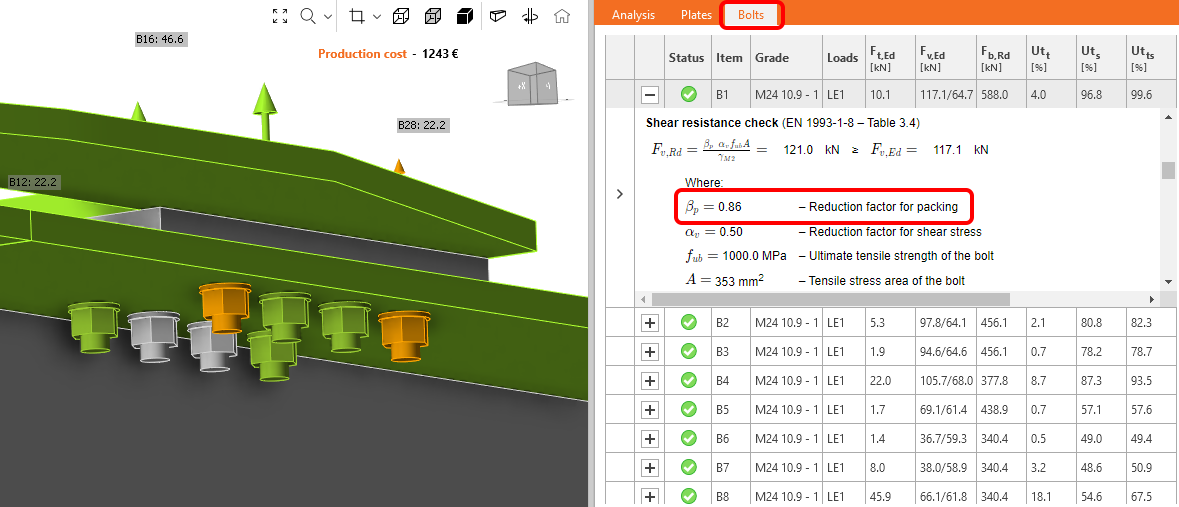
The reduction factor βp is taken into account and displayed in the check equation by default. It can be turned off in the Code setup.
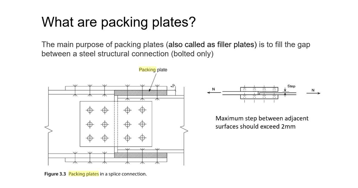
Filler plates (in other terminology, packing plates) are used to fill the gap in bolted connections when aligning connections of plates with different thicknesses.
Available in IDEA StatiCa Steel and IDEA StatiCa Complete editions.
Essayez les nouvelles fonctions d'IDEA StatiCa aujourd'hui
Detailing improvements for bolts and welds in Eurocode
Satisfying detailing checks are essential for a correct and safe design.
The detailing checks for bolts and welds in the IDEA StatiCa Connection application have been extended by new rules according to Eurocode.
Implemented range of validity rules:
Bolts according to EN 1993-1-8 and EN 1993-1-3
- Minimum plate thickness
- Ductility check
Welds according to EN 1993-1-8
- Minimum plate thickness
- Minimum weld throat thickness of fillet welds
- Ductility check
The application distinguishes four types of detailing messages:
- OK - represented by the green tick button

This indicates that the model complied with all necessary matters according to the standard, and the connection is designed safely.
- Error - represented by the red cross icon

Error alerts you to serious non-compliance with the requirements of the standard, and you have to pay attention to the design of the corresponding component.
- Warning - represented by the yellow triangle with an exclamation point icon

Warning message provides you with recommendations, e.g., based on practical experience. Raised attention to the design is advised but not unconditionally necessary.
- Info - represented by the blue info icon

Info message has an informative character about less common issues to check, e.g., ductility.
Individual messages can be seen in detail in corresponding check tables under formulas in the Check section or in the Report.
If there is more than one detailing message of a different type for one item, then the resulting status of messages of the particular item is determined by the message of the highest importance.
The "Error" message has the highest importance, the "Info" message has the lowest one.
The theory, including all corresponding formulas for the above-mentioned checks, is described in part of the theoretical background - Check of steel connection components (EN).
Available in IDEA StatiCa Steel and IDEA StatiCa Complete editions.
Download the new version of IDEA StatiCa and try all the features
Limitations to checks of anchors
Eurocode
Anchor type: Straight
Message:
The following checks of anchors loaded in tension are not provided and should be checked using the information in the relevant European Technical Product Specification:
- Pull-out failure of fastener (for post-installed mechanical anchors) – EN 1992-4, Cl. 7.2.1.5,
- Combined pull-out and concrete failure (for post-installed bonded anchors) – EN 1992-4, Cl. 7.2.1.6,
- Concrete splitting failure – EN 1992-4, Cl. 7.2.1.7.
Concrete blow-out failure is provided only for anchors with washer plates.
Anchor type: Washer plate
Message:
Concrete splitting failure should be determined by EN 1992-4, Cl. 7.2.1.7. The information from relevant European Technical Product Specification is missing.
AISC (LRFD)
Anchor type: Straight
Message:
The following checks of anchors loaded in tension are not provided and should be checked using the information in the relevant Technical Product Specification (based on the 5 % fractile of tests performed and evaluated according to ACI 355.2):
- Pull-out failure of fastener (for post-installed mechanical anchors) – ACI 318-19: 17.6.3,
- Bond strength of adhesive anchor (for post-installed bonded anchors) – ACI 318-19: 17.6.5,
- Concrete splitting failure during installation should be evaluated by ACI 355.2 requirements.
Concrete blow-out failure is provided only for anchors with washer plates.
Anchor type: Washer plate
Message:
Concrete splitting failure during installation is not checked and should be evaluated by ACI 355.2 requirements.
CSA
Anchor type: Straight
Message:
The following checks of anchors loaded in tension are not provided and should be checked using the information in the relevant Technical Product Specification (based on the 5 percent fractile of tests):
- Pull-out failure of fastener (for post-installed mechanical anchors) – CSA A23.3-14: D.6.3,
- Bond strength of adhesive anchor (for post-installed bonded anchors) – CSA A23.3-14: D.6.5.
Concrete blow-out failure is provided only for anchors with washer plates. Anchors shall satisfy the required edge distances, spacings, and thicknesses to preclude splitting failure as required by CSA A23.3-14: D.9.
Anchor type: Washer plate
Message:
Anchors shall satisfy the required edge distances, spacings, and thicknesses to preclude splitting failure as required by CSA A23.3-14: D.9.
AS
Anchor type: Straight
Message:
The following checks of anchors loaded in tension are not provided and should be checked using the information in the relevant Technical Product Specification (testing according to AS 5216:2018: Appendix A):
- Pull-out failure of fastener (for post-installed mechanical anchors) – AS 5216:2018: 6.2.4,
- Combined pull-out and concrete cone failure (for post-installed bonded anchors) – AS 5216:2018: 6.2.5,
- Concrete splitting failure – AS 5216:2018: 6.2.6.
Concrete blow-out failure is provided only for anchors with washer plates.
Anchor type: Washer plate
Message:
Concrete splitting failure should be determined by AS 5216:2018: 6.2.6. The information from relevant Technical Product Specifications (testing according to AS 5216:2018: Appendix A) is missing.
Available in IDEA StatiCa Steel and IDEA StatiCa Complete editions.
Download the new version of IDEA StatiCa and try all the features
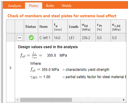
Detailed calculation of connection design material values displayed for plates
For different types of analysis, the design material parameters' values change according to the particular design code's requirements.
If the user wants to display and check the design values going into the analysis calculations, everything can be found in the result table for Plates. Simply click the 'plus' button to display more comprehensive information about the analysis, such as material reduction for hollow sections or specific steel parameters for stress-strain analysis, capacity design, fire design, or horizontal tying analysis.

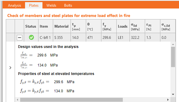
Available in IDEA StatiCa Steel and IDEA StatiCa Complete editions.
Essayez les nouvelles fonctions d'IDEA StatiCa aujourd'hui
Limitations to checks of anchors
Eurocode
Anchor type: Straight
Message:
The following checks of anchors loaded in tension are not provided and should be checked using the information in the relevant European Technical Product Specification:
- Pull-out failure of fastener (for post-installed mechanical anchors) – EN 1992-4, Cl. 7.2.1.5,
- Combined pull-out and concrete failure (for post-installed bonded anchors) – EN 1992-4, Cl. 7.2.1.6,
- Concrete splitting failure – EN 1992-4, Cl. 7.2.1.7.
Concrete blow-out failure is provided only for anchors with washer plates.
Anchor type: Washer plate
Message:
Concrete splitting failure should be determined by EN 1992-4, Cl. 7.2.1.7. The information from relevant European Technical Product Specification is missing.
AISC (LRFD)
Anchor type: Straight
Message:
The following checks of anchors loaded in tension are not provided and should be checked using the information in the relevant Technical Product Specification (based on the 5 % fractile of tests performed and evaluated according to ACI 355.2):
- Pull-out failure of fastener (for post-installed mechanical anchors) – ACI 318-19: 17.6.3,
- Bond strength of adhesive anchor (for post-installed bonded anchors) – ACI 318-19: 17.6.5,
- Concrete splitting failure during installation should be evaluated by ACI 355.2 requirements.
Concrete blow-out failure is provided only for anchors with washer plates.
Anchor type: Washer plate
Message:
Concrete splitting failure during installation is not checked and should be evaluated by ACI 355.2 requirements.
CSA
Anchor type: Straight
Message:
The following checks of anchors loaded in tension are not provided and should be checked using the information in the relevant Technical Product Specification (based on the 5 percent fractile of tests):
- Pull-out failure of fastener (for post-installed mechanical anchors) – CSA A23.3-14: D.6.3,
- Bond strength of adhesive anchor (for post-installed bonded anchors) – CSA A23.3-14: D.6.5.
Concrete blow-out failure is provided only for anchors with washer plates. Anchors shall satisfy the required edge distances, spacings, and thicknesses to preclude splitting failure as required by CSA A23.3-14: D.9.
Anchor type: Washer plate
Message:
Anchors shall satisfy the required edge distances, spacings, and thicknesses to preclude splitting failure as required by CSA A23.3-14: D.9.
AS
Anchor type: Straight
Message:
The following checks of anchors loaded in tension are not provided and should be checked using the information in the relevant Technical Product Specification (testing according to AS 5216:2018: Appendix A):
- Pull-out failure of fastener (for post-installed mechanical anchors) – AS 5216:2018: 6.2.4,
- Combined pull-out and concrete cone failure (for post-installed bonded anchors) – AS 5216:2018: 6.2.5,
- Concrete splitting failure – AS 5216:2018: 6.2.6.
Concrete blow-out failure is provided only for anchors with washer plates.
Anchor type: Washer plate
Message:
Concrete splitting failure should be determined by AS 5216:2018: 6.2.6. The information from relevant Technical Product Specifications (testing according to AS 5216:2018: Appendix A) is missing.
Available in IDEA StatiCa Steel and IDEA StatiCa Complete editions.
Download the new version of IDEA StatiCa and try all the features
Detailed calculation of connection design material values displayed for plates
For different types of analysis, the design material parameters' values change according to the particular design code's requirements.
If the user wants to display and check the design values going into the analysis calculations, everything can be found in the result table for Plates. Simply click the 'plus' button to display more comprehensive information about the analysis, such as material reduction for hollow sections or specific steel parameters for stress-strain analysis, capacity design, fire design, or horizontal tying analysis.
Available in IDEA StatiCa Steel and IDEA StatiCa Complete editions.
Essayez les nouvelles fonctions d'IDEA StatiCa aujourd'hui
It is also worth mentioning that we have updated steel and bolt grade materials for AISC360-22 in the application. (since patch 23.0.4)
Steel member design
Detailed calculation of connection design material values displayed for plates
For different types of analysis, the design material parameters' values change according to the particular design code's requirements.
If the user wants to display and check the design values going into the analysis calculations, everything can be found in the result table for Plates. Simply click the 'plus' button to display more comprehensive information about the analysis, such as material reduction for hollow sections or specific steel parameters for stress-strain analysis, capacity design, fire design, or horizontal tying analysis.
Available in IDEA StatiCa Steel and IDEA StatiCa Complete editions.
Essayez les nouvelles fonctions d'IDEA StatiCa aujourd'hui
Strengthening of existing steel members
Construction stages and strengthening
Construction stages (known as Preload in the Member application) are used when, say, an engineer needs to check a member based on a new load distribution against an existing load pattern. Using this method, specific and targeted strengthening works can be designed.

Strengthening a building, rather than demolition, can be a complex solution, which is why this method has been introduced. It aims to allow design teams to formulate a strategy that saves buildings and reduces CO2 emissions. There are several examples in engineering where this is required: where solar PV panels are used on existing roofs, leading to increased loading and uplift, or re-modeling of retail premises where stairs and openings are never in the right place.

Define a new Check type of the pre-load to allow the software to introduce additional loading after the required ULS loading checks have been completed. Thanks to this, you can clearly see pass/fail results, including the, e.g., stress in the existing structure, and in the plates of the added strengthening.
Available in IDEA StatiCa Steel and IDEA StatiCa Complete editions.
Essayez les nouvelles fonctions d'IDEA StatiCa aujourd'hui
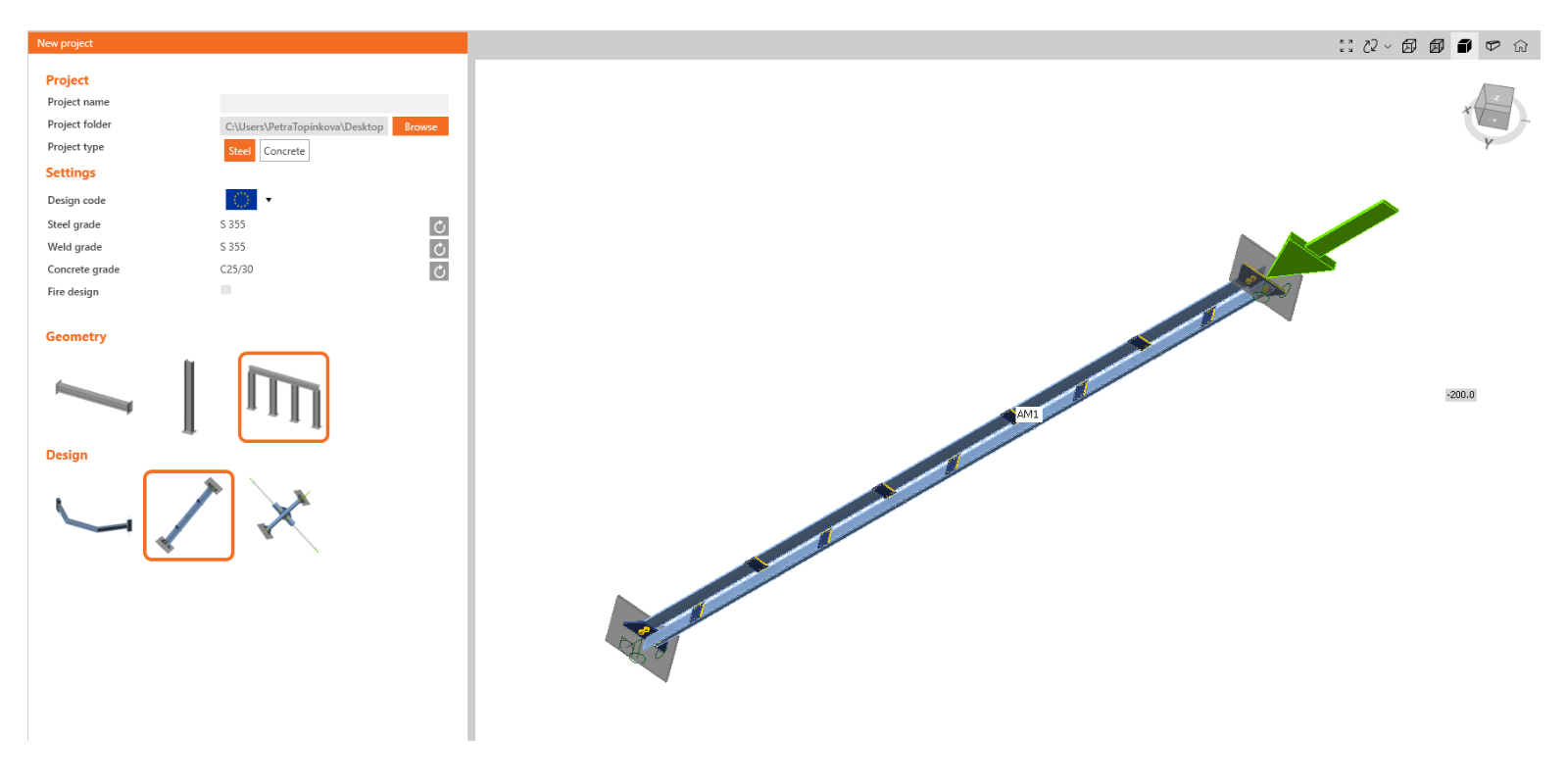
Modeling wizard for typical use-cases in Steel Member
Modeling Wizard
Whether you're unsure of how to properly define elements, boundary conditions, and loads, or you want to create a one-click project, you can use the modeling wizard. Templates exist for the most common use cases. All you need to do is to choose the one that matches your specifications and modify it according to your project's requirements.
The templates are divided into three basic categories based on geometry:
- Beam
- Column
- General
There are then several design options for each category.
Various typical examples are created for a beam, including haunched beams or beams with openings:

For a column, these are mainly isolated elements anchored into the concrete footing with different levels of strengthening:

In the general section, you can find, among other things, examples of bracing diagonals.
As already mentioned, this feature is created based on examples from users as a tool for easier and more efficient work with the application. If you are missing a typical example here, feel free to contact us with your suggestions.
Available in IDEA StatiCa Steel and IDEA StatiCa Complete editions.
Essayez les nouvelles fonctions d'IDEA StatiCa aujourd'hui
Singularity detection in Member
If the model of Member is imperfect in terms of modeling (e.g., a stiffener plate is not welded to the beam or some connection is missing), the singularity message will appear after pushing the Calculate button, and the analysis is stopped.
This was a problem, especially in large Member models where it was difficult to identify which part of the model caused the singularity.
With the new version, the message with the description of the problematic part is shown in the 3D window, and the missing connection can be easily fixed. In case there are more singularities, the first failing part is shown, and after it is fixed, the other is revealed.
Available in IDEA StatiCa Steel.
Download the new version of IDEA StatiCa and try all the features
Design of walls, details, and cross-sections
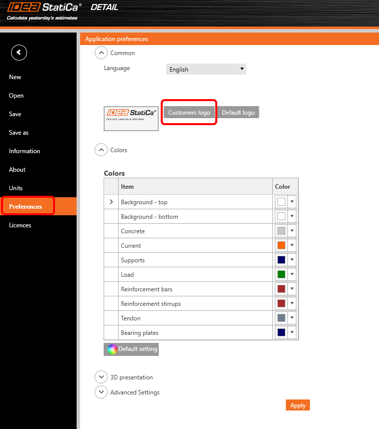
Intuitive ribbon and navigation system for IDEA StatiCa Detail
Work in an attractive, clear, and simple-to-use graphical user interface (GUI) to make your concrete structural design faster!
Application layout
The graphical user interface of the Detail app is clear to understand and simple to use:
- Made up of six ribbon tabs – Project, Design, Tools, Check, Report, and Materials
- Triggering functionality or interacting with dialog boxes is done by command buttons in ribbon groups
- The scene displaying the user's concrete structure design and the navigation tree on the left takes up a lot of screen space as they are the most important components for the user
- The properties of a selected item (entities can be selected in the tree or in the scene) are presented in the Property grid on the right side of the app
- The footer at the bottom part of the app contains basic information about project settings, such as the design code, rounding units, presentation units, and a link to our webpage. By clicking these entities, the dialog window with relevant settings is open, allowing the definition of a selected group of parameters.

The project tab or backstage menu offers:
- Basic commands, such as New, Open, Save, and many more
- Users can find application settings such as Units or Preferences here


Adding a new project entity:
- Each project can contain multiple project items
- A new project item is added using commands in the ribbon or in the backstage menu - Information tab
- It is possible to copy an existing item when working on similar structural designs

How to work in the Detail app
The graphical user interface is very intuitive and guides users on how to create their projects efficiently. Just follow the tabs in the ribbon step by step.
New project
- A wizard allows defining a project from a template (or user-defined type of structure) and setting initial material properties
Design
- Serves for designing the structural member, including the load and definition of reinforcement
- The geometry of the structure and reinforcement can be easily imported from the DXF files or added here by relevant buttons
- The tree of entities contains all entities defined in a model. Every entity in the tree has a set of carefully selected commands in the context menu. Entities in the tree can be grouped according to type or as a list of entities ordered sequentially.
- Great functionality that helps to design reinforcement has been developed. By deactivating the command "Draw rebar" in the ribbon, just the selected rebar entity is displayed in the scene and the rest is hidden. This helps with the detailing of a selected rebar without interfering with many other existing rebars.


Tools
- For all engineers struggling with designing a sufficient amount and layout of reinforcement, it allows calculation methods such as topology optimization and linear analysis to determine areas of the structure that require reinforcement
- The tree of entities is reduced and contains all existing rebars only
- The "Draw rebar" button, whose function is described in the section Design, can be used here, too
- For a reduced view on rebars described in the previous section (Design tab,) easy reinforcement design can be used in the Tools tab as well

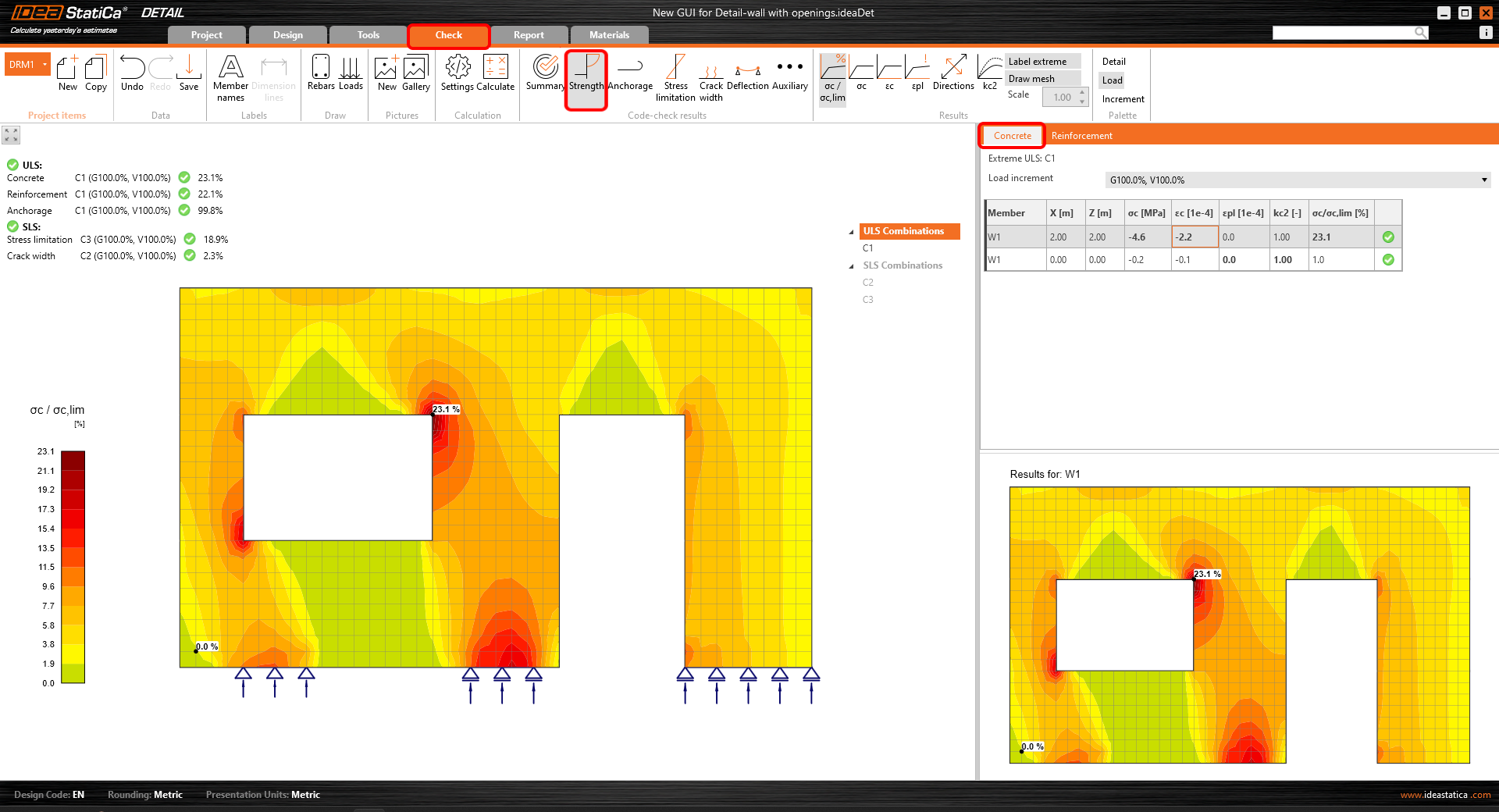
Check
- The reduced navigation tree contains just combinations active for the code-check
- The type of code-check is selected by clicking the button in the ribbon (group Code-check results)
- Results for each material type are presented separately in the scene. Users can select what results are presented by selecting the tab Concrete, Reinforcement, or Tendon in the property grid


Report
- Several types of reports are supported – a brief report and a detailed one or a bill of materials if needed
- In the detailed report, users can arbitrarily define what results and outputs are presented in the final document, meaning a fully customizable report
- The report can be exported to a DOC or PDF file

Materials
- Check out the stress-strain diagram of each material, concrete, reinforcing, or prestressing steel
- Modify the material properties if necessary

Designing and checking concrete structures in the new GUI for the Detail application is fast and easy. How do we know? Because this user interface has worked very well for millions of customers using the Connection application, which is the basis of the new Detail GUI.
Essayez les nouvelles fonctions d'IDEA StatiCa aujourd'hui
Interaction code-check advancements in RCS
In the following article, we will explain the approach to the calculation of the longitudinal force caused by shear Ftd,s. This method consists mainly of changing the way the force is applied to the cross-section. We start with the definition of the cross-section subjected by N-My-Mz and then we gradually add the longitudinal force caused by shear and torsion.
Response N-My-Mz
The cross-section is, in the first phase, loaded by a combination of normal force and bending moments N-My-Mz. The results comparison between the software versions provides us with the same results.

If the shear reinforcement is designed in the cross-section, shear can be resisted by a fictitious strut-and-model composed of stirrups, concrete struts, and longitudinal rebars.

Calculated longitudinal force due to shear is applied to the cross-section with all components (concrete and rebars). The initial stress state taken from the N+My+Mz response is already defined for each component.
The equation for the calculation of the longitudinal force due to shear:
\[\Delta F_{td,s} = V_{ed}(cot \theta -cot \alpha ) \]
Longitudinal force Ftd,s is, by default, applied to:
- The centroid of the section resisting shear – for the cross-sections where the application is able to define such a section (the red area in the following figure).

- The centroid of the cross-section – for the cross-sections where the application is not able to define such a section.
Interaction N-My-Mz-Vz
The sectional response due to the combination of N+My+Mz+ΔFtd,s is calculated. We can notice that the stress in concrete and rebars in compression decreased while the stress in tensile reinforcement increased (in comparison with response N+My+Mz). The section is still in equilibrium.

Interaction N-My-Mz-Vz-T
For sections also subjected to torsion, we apply an additional longitudinal tensile force ΔFtd,t to longitudinal rebars lying inside the stirrup selected for torsion check. The calculation model is slightly different because we assume that the section is composed of longitudinal rebars while neglecting the concrete. The N+My+Mz+ΔFtd,s response defines each rebar's initial stress state. Consequently, ΔFtd,t is applied, following the condition of the same strain increment for all rebars resisting torsion.

The assumptions for the calculation mean that in some cases, like sections located above the intermediate support of a continuous beam, different results can be observed. When the stress in tensile reinforcement due to N+My+Mz reached yield stress, other less utilized rebars carried the longitudinal force due to shear (e.g., located in a compression zone).
Available in IDEA StatiCa Concrete and IDEA StatiCa Complete editions.
Essayez les nouvelles fonctions d'IDEA StatiCa aujourd'hui
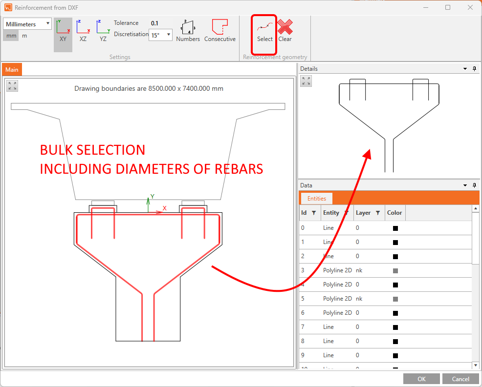
Importing reinforcements from DXF files in IDEA StatiCa Detail
Reinforcement DXF import improvements in IDEA StatiCa Detail
Such functionality has been in the Detail app for a while, and we are constantly improving it according to your needs. Now we are adding the possibility to import all the reinforcement drawn in dxf with respect to its diameter if defined as a global width of a curve. You can import the whole reinforcement layout with various diameters of rebars in one click!

Essayez les nouvelles fonctions d'IDEA StatiCa aujourd'hui
BIM links and education
BIM links reduce modeling time, decrease the number of copy-paste errors, and overcome any issues with data transference. In version 23.1, you can now access our new BIM link with SDS2 by Allplan as well as an IDEA StatiCa plugin for the Rhino Grasshopper tool.
IDEA Grasshopper plugin
About Rhino/Grasshopper
Rhino and Grasshopper is a powerful CAD modeling platform with a large array of plugins available for the architectural and engineering industry. As a parametric modeling tool, Grasshopper has created an extensive and well-maintained ecosystem of third-party plugins, interacting through their powerful geometry engine. Tekla, Revit and all major FEA software have plug-ins for Grasshopper.
How the plugin works
The Grasshopper plugin enables users to interact with IOM and the Connection API using a 'low code' visual programming approach.
Combining Grasshopper with IDEA StatiCa's Open Model and APIs creates an extremely powerful platform for the parametric definition of complex connection geometry plus the automation and optimization of connections.
Linked applications: IDEA Open Model, IDEA StatiCa Connection, IDEA StatiCa Checkbot (Standalone)
The comprehensive description of the IDEA plugin for Grasshopper with 'How to model Examples' is presented on the webpage Rhino to IDEA StatiCa workflow.
Essayez les nouvelles fonctions d'IDEA StatiCa aujourd'hui
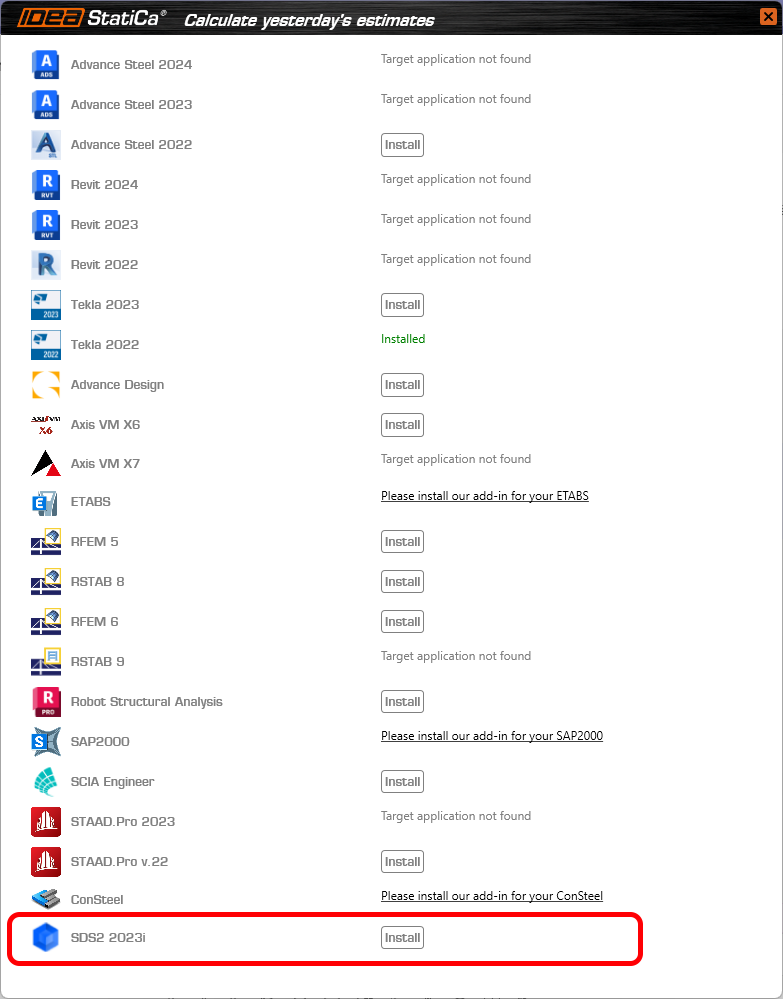
BIM link with Allplan SDS2
The Link provides the ability for users to directly transfer fully detailed connections in either a single or bulk selection manner. The user can transfer connection elements such as bolts, welds, stiffeners, and plate cuts modeled in SDS2 detailing tool directly into IDEA StatiCa Checkbot and further into the Connection app.
The integration is displayed in the list of fully supported third-party software during the BIM installation process.
A comprehensive description of the IDEA plugin for SDS2 is presented on this webpage.
Essayez les nouvelles fonctions d'IDEA StatiCa aujourd'hui
UX features in parametric design
This makes parameters a usable feature to drive powerful parametric and automated connection modeling.
UX
The UX of the Developer tab has significant features included.
- Parameters and model properties are now split into tabs in the side panel. With Parameters being positioned as the 'primary' element of this functionality.
- It is possible to link parameters to model properties directly from this tab using the add model property link button.

- A Value output column has been included so the user can see the calculated output in real-time.
- A custom Parameter Validation is available to allow template creators to notify others of limitations to their parametric designs.
- The user can select a validation 'type' and choose whether to warn the user or restrict the set to the model.
- If validation is set and passed (=true), a success icon displays.
- If validation is set and not passed (=false), either a warning or error icon displays.
- If no validation is set, no icon displays.

- A unit selection is available to allow users to see the output value in their preferred unit type (set by program settings). Note: all calculations and expression inputs are still to be in basic SI units.

- The Model Property Dialogue works in the following way:
- An Is active column has been added to model properties to show the user if the specific property is visible in the current UI of the program.
- A parameter can now also be edited on a particular added model property.
The IDEA StatiCa development team also looks to take a step further toward parametric templates and the automatic application of standard and simple connections.
Please also see the introduction description in Setting up parametric design with Developer Tab knowledge base article.
Available in IDEA StatiCa Steel and IDEA StatiCa Complete editions.
Download the new version of IDEA StatiCa and try all the features
BimApi solution for AXIS VM 7, Robot Structural Analysis 2024
New BIMapi links
The links to AXIS VM7 and Robot Structural analysis have been available since the patches of 23.0.
This makes it stable, reliable, less prone to create unnecessary errors, and most importantly faster!
When it comes to Robot Structural Analysis we are now able to read eccentricities of 1D elements when importing the model to our Checkbot application. This is a feature that has been loudly asked about by the Robot users. You asked for it, we delivered!
Limitations
Be aware that if you have a project created with BIM link in version 23.0 of IDEA StatiCa and you update to new version of 23.1, you might not be able to read the project due to new BIMapi solution. Therefore, we recommend to finish existing projects with version 23.0.
How to activate the BIM links
Download and install the latest version of IDEA StatiCa. Open IDEA StatiCa and continue to the BIM tab. There, you click Activate your BIM link...
You can find a list of supported FEA/BIM solutions here.

A window pops up asking you "Do you want to allow this app to make changes to your device?" Confirm by selecting Yes.
The BIM links for AXIS VM7 and Robot Structural Analysis 2024 are automatically installed. You can find the status of each BIM link.

Tutorials
You can follow the step-by-step tutorials to learn how to streamline your workflow.
Essayez les nouvelles fonctions d'IDEA StatiCa aujourd'hui
Site web de documentation de l'API/du développeur
Où le trouver ?
La page developer.ideastatica.com est l'endroit où vous devez aller.
Ce nouveau site de documentation pour les développeurs offre aux développeurs tiers d'IDEA StatiCa et aux scripteurs d'API un point d'accès unique aux informations relatives aux services publics et à la norme d'IDEA StatiCa.
Le site relie la documentation statique, la documentation de la norme et des exemples spécifiques.
Améliorations par rapport au système précédent
- La page web publique de GitHub fournit de nombreuses informations utiles, mais il n'est pas toujours facile d'y naviguer. C'est pourquoi ce système offre aux développeurs un point d'accès unique.
- Les notes de mise à jour sur les ruptures permettent aux développeurs de savoir quand et comment ils doivent mettre à jour leurs applications tierces.
- Il permet de faire la distinction entre les développements WIP publics (qui ne devraient pas être utilisés comme des produits) et ceux qui sont des produits fonctionnels accompagnés d'une documentation.
- Le Wiki permet de créer une documentation sur la norme et de la relier aux classes et aux concepts.
- Le Wiki est automatiquement mis à jour et entretenu.
- Les exemples sont facilement accessibles à partir de la documentation.
Le site est divisé en quatre sections distinctes :
- IDEA Open Model (IOM), relatif à la création et à la spécification du modèle de données IOM.
- Liens MIB (MIB API), relatifs à la création de liens MIB Checkbot à l'aide du cadre MIB API.
- Design API (API), relatif aux API des applications de conception.
- Extensions, relatives aux extensions créées à partir des API de l'application de conception.
API pour les mises à jour de IDEA StatiCa Connection
La mise à jour de l'API pour IDEA StatiCa Connection inclut des fonctionnalités permettant d'élargir son utilisation, telles que :
- Présentation de l'assemblage
- Positionnement des éléments
- Conception automatique des soudures
- Contrôleur de paramètres partagés
- Génération de rapports améliorés
- Conversion de la norme du projet

Disponible dans IDEA StatiCa version 25.1.
Essayez les nouvelles fonctions d'IDEA StatiCa aujourd'hui
Check the compatibility with your software in the list of supported versions in 23.1
To help you master IDEA StatiCa, we redesigned Campus, which provides you with self-paced e-learning courses, each with the option of obtaining professional-level certification.