
Structural design of a concrete bridge diaphragm (EN)
1 New project
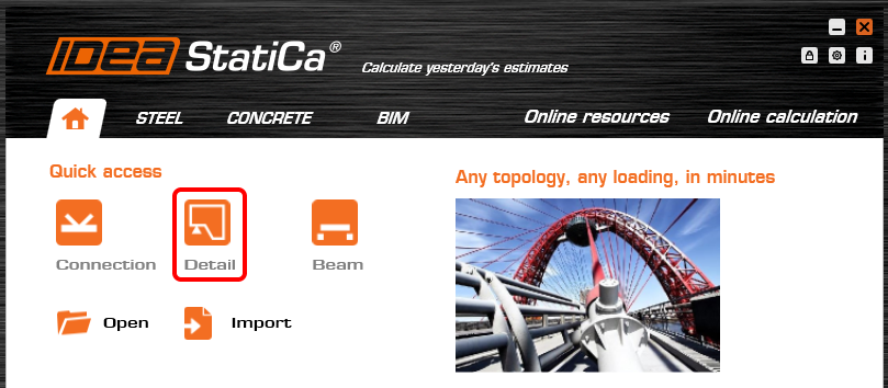
Start a New project in IDEA StatiCa Detail.
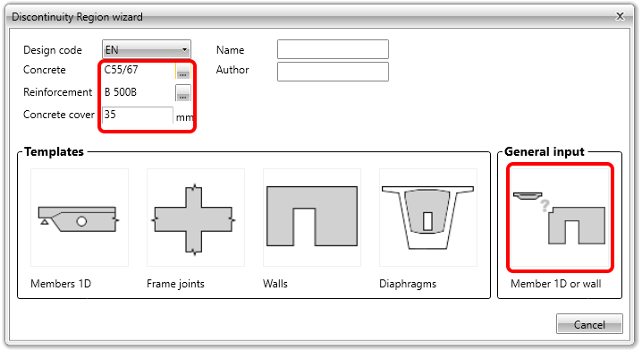
In the Discontinuity Region Wizard set the concrete and reinforcement grade and we define the Concrete cover thickness. You will not use any template but select the option of General input.
2 Geometry
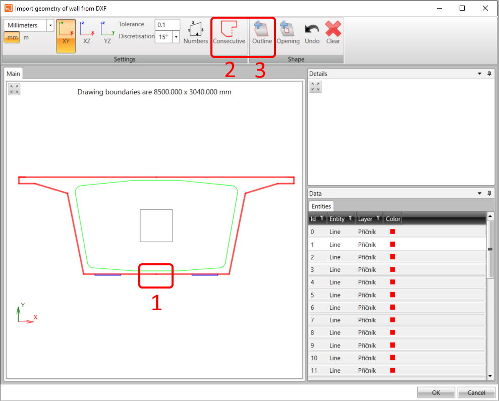
Create the geometry of the diaphragm via the Import DXF button.

Select the Diaphragm.dxf file.

Select the polyline and using the Consecutive and Outline commands create the shape.
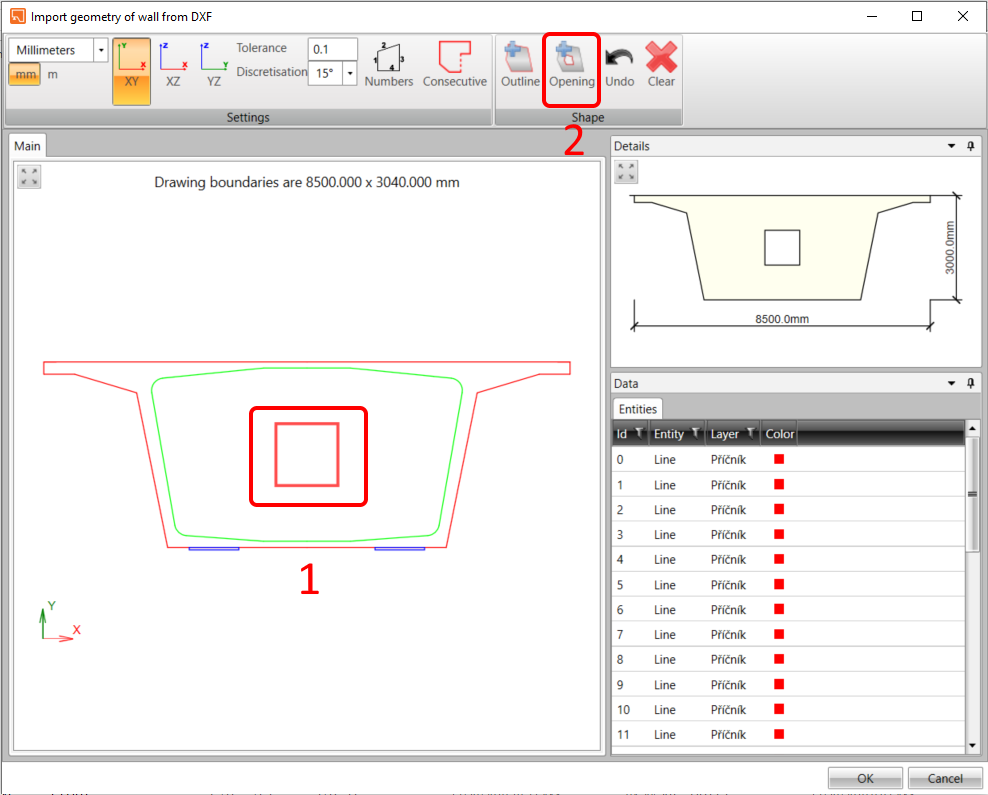
To create the opening in the diaphragm, click on the polyline in the main window and then the button Opening. We finish the whole process by clicking on the OK button.
The geometry of the model is done by the shape and Thickness. Set the value to 1.2 m.

Let’s place the opening 0.4 m from the bottom edge of the diaphragm.

The diaphragm itself is statically overdetermined so you need to input the boundary conditions. Add the support using the Plus button, the type of support will be the Point bearing plate.

Left support represents the bearing with constraints in X and Z direction. Width and Thickness of the bearing plate are set as 0.8 m and 0.08 m, respectively. The bearing is located 0.75 m from the left edge and is related to edge number 9.

Copy the PS1 and release it in the X-direction. The alignment of the support will be From end.

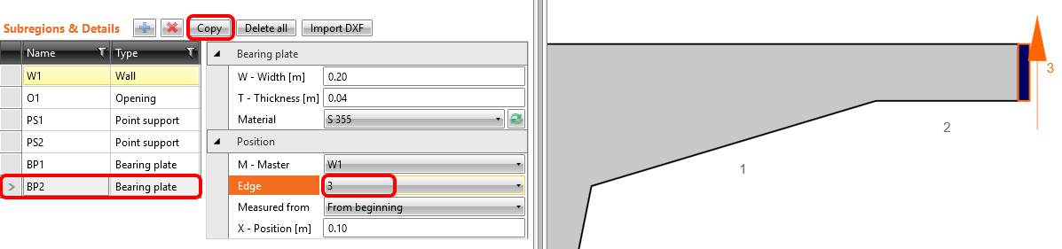
Apply transverse prestressing by straight tendons located in an upper slab of the section, so it is necessary to input the Bearing plate to be able to transfer the force from prestressing anchorage to concrete.

Width and Thickness of the plate is set to 0.2 m and 0.04 m, respectively. We put the plate on the edge 5 with offset 0.1 m.

Copy the operation BP1 and change the edge to 3.
3 Load effects
Start with the definition of loads that act on the diaphragm.
The first load case is automatically generated by the software. Rename the load case to Self-weight and set Type as Permanent. The correct definition of the load case type is an important step for the evaluation of SLS and ULS results.

- Switch to Load impulses where we input Surface load which represents the Self-weight of the diaphragm.

The intensity of the surface load is -30 kN/m2.

In the next step add load impulse in the form of Line loads.
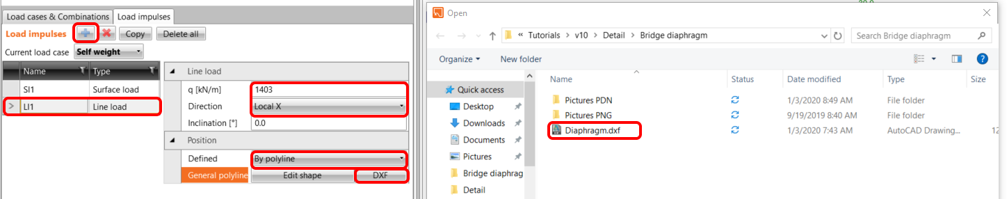
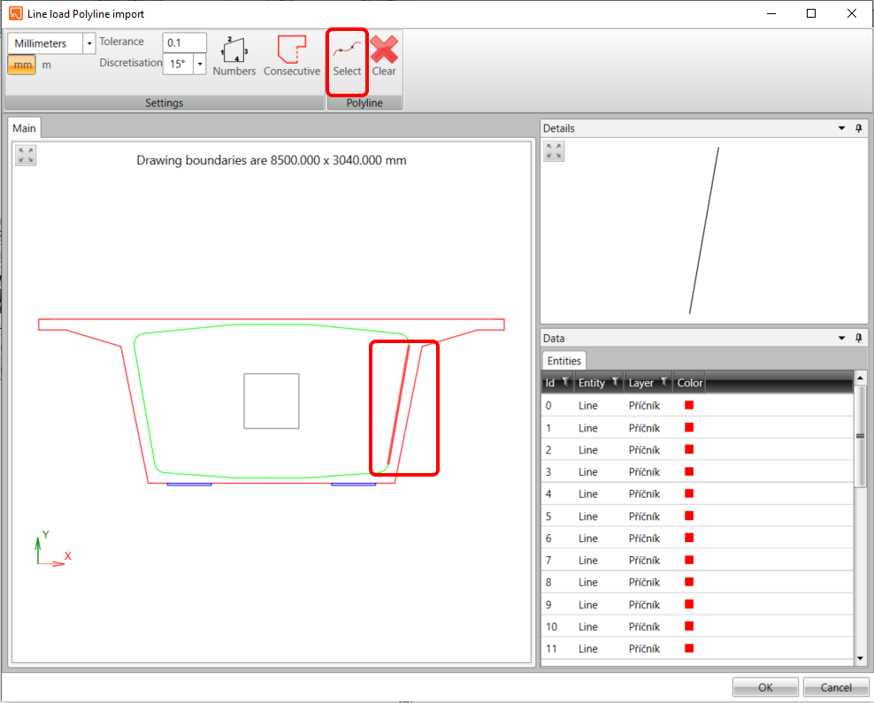
The load LI1 represents the self-weight of the bridge structure which is transferring through the webs of the box girder section to the diaphragm and subsequently to the bearings. Intensity of the load is 1403 kN/m in the local direction X and the position will be defined by Polyline. Use DXFreference Diaphragm.dxf.
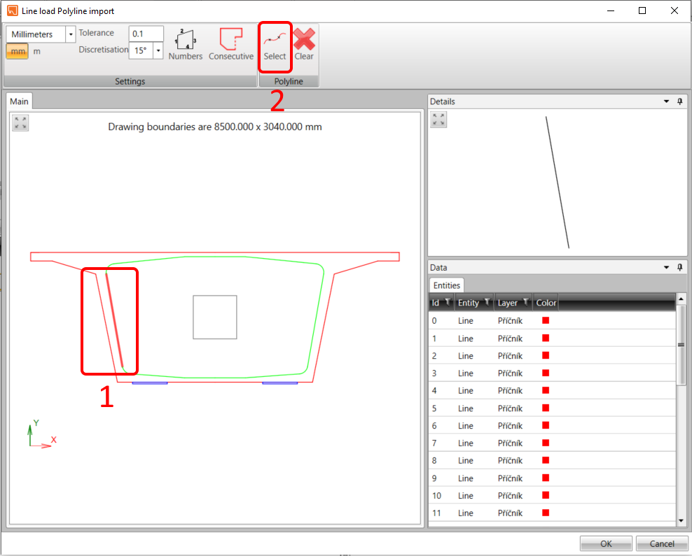
Indicate a left midline of the web (1) and push Select(2) button for putting the line load on it.
In the same way put the load on the second web. At first Copy operation LL1 and use DXF reference Diaphragm.dxf to put the line load.

Indicate a right midline of the web and push the Select button for putting the line load on it.
Since the global model is consisted of a continuous bridge beam, there are secondary effects due to longitudinal prestressing acting on the diaphragm.
Add a new load case and set the type as Permanent.

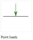
Add the Point load to represent the tendon force.
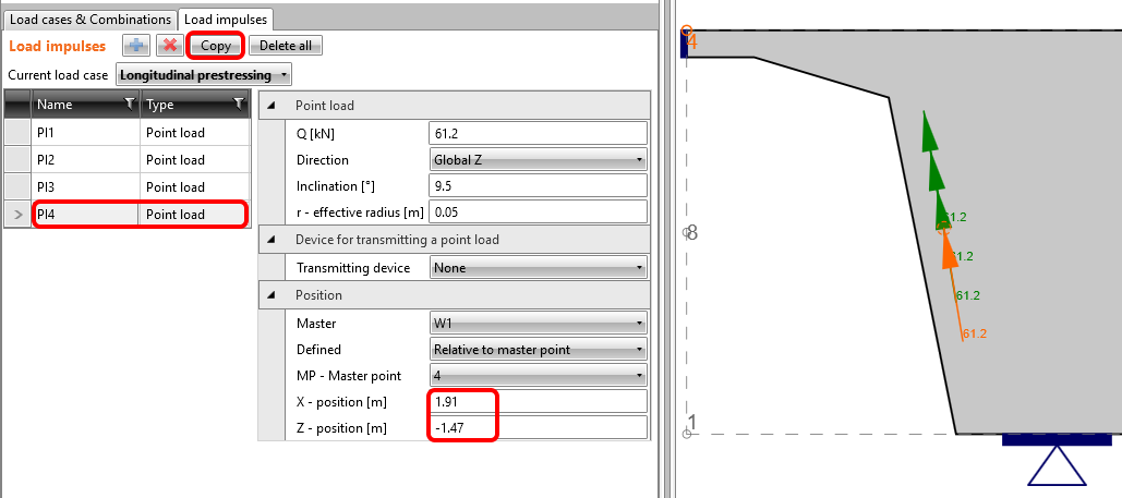
The secondary effects due to longitudinal prestress cause tensile reactions in the bearings whose value is 61.2 kN per tendon. That is why the direction of the forces is opposite from reactions in the bearings and they are slightly inclined in 9.5 degree since it is supposed to correspond with the centerline of the web of girder box section. The transfer of forces directly to the concrete part is ensured by effective radius. The effective radius should represent the radius of the tendon. We input 0.05 m. The coordinates of the center of the acting force are related to point 4.

Copy PI1 and change the coordinates of the next tendon force.

Copy PI2 and change the coordinates of the next tendon force.

Copy PI3 and change the coordinates of the next tendon force.
Copy PI4 and change the Master point to 3. The Inclination is set with negative sign -9.5 degree.

Copy PI5 and change the coordinates of the next tendon force.

Copy PI6 and change the coordinates of the next tendon force.

Copy PI7 and change the coordinates of the next tendon force.

Copy the load case of the Self-weight and rename the new load case as a Superimposed dead load.

Delete the surface load. In the Load impulses tab only change the intensity of LI3 to 300 kN/m.

Change the intensity of LI4 to 300 kN/m.

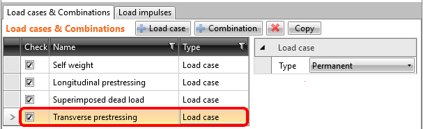
The next load case will be named Transverse prestressing.
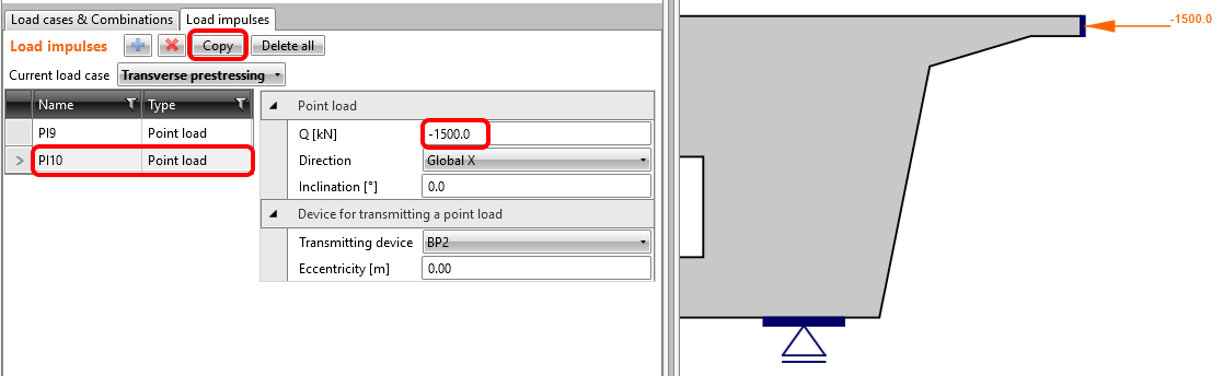
Add the Point load representing the prestressing force from the unbonded straight tendons.

The magnitude of the force is 1500 kN in the Global X direction. The force is transmitted into concrete by Base plate BP1.

Copy PL9 and change the value to -1500 kN.
Now, create a Variable load case which represents torsion and shear effects due to eccentric traffic load. Name the load case as Shear stress flow from traffic load.

Add load impulse in the form of Line loads.

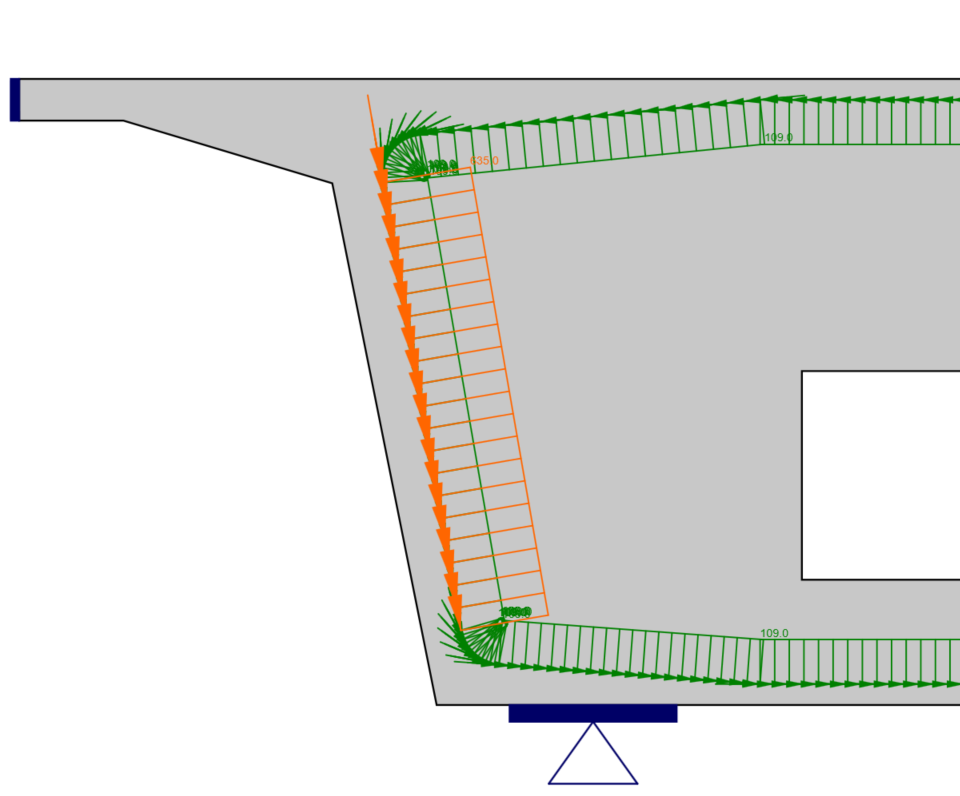
The intensity of the load is set to 109 kN/m. To input, the curve, use the definition by Polyline and select also DXF reference Diaphragm.dxf. This load represents shear stress flow by which the effects of torsion are transmitted by the webs and slabs of the girder box cross-section.

Select(1) the midline curve which represents an area of shear stress flow by torsion. As the second step push Consecutive (2) to all curves was indicated and finally Select (3) item finish the whole process of assignment the line load on it.

Shear stress flow is caused by torsion.

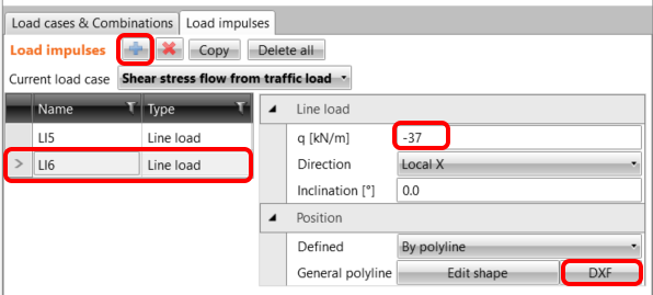
You cannot forget the shear effects due to eccentric load which is transmitted by the webs of the girder box section.
Copy LI5 and change the intensity to -37 kN/m. The Position will be defined by Polyline. Use same approach as for the Self-weight.

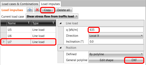
Copy LI6, change the intensity to 635 kN/m.
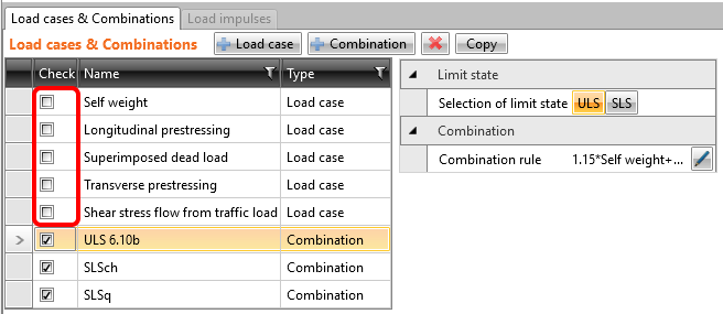
The nonlinear combinations were already defined: C1 stands for ULS checks. C2 is a quasi-permanent and C3 is a characteristic load combination, both defined for SLS code checks (see the tab Load cases & Combinations). The partial load factors for the combination rules can be adjusted as well.
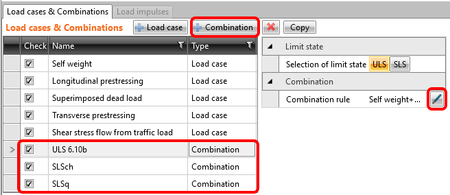

As you do not need to evaluate the individual load cases, they are unchecked which implies that they will not be analyzed. The calculations will be performed only for the checked items (combinations C1, C2 and C3).
4 Reinforcement
Before you proceed to Reinforcement design check out Design tools (1) and run the Topology optimization (2) which shows us the tension and compression fields with respect to acting loads. After the analysis, go to reinforcement design by clicking on Input/Edit button (3).

According to the tensile areas resulting from topology optimization input the reinforcement. Start with the GB1 which is placed on the bottom part of the diaphragm. Put 3 layers of reinforcement which contain 5 bars in a layer. Set the standard hook as anchorage type at both ends of the rebar.

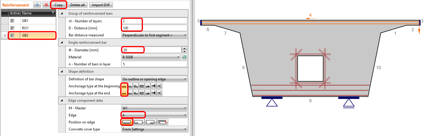
Input a cage around the opening, which will cover the tensions in the corners and decrease the development of cracks in the vicinity of the opening. The bars will have Perfectly bonded anchorage type which ensure shorter anchorage length for rebars.

Copy GB1 and change the number and diameters of rebars for GB2.
Like the last type of reinforcement, we add wire fabric WF1 which has the diameter for all rebars 14 mm and the distances between the rebars will be 150 x 150 mm in both directions. There are 5 layers of wire fabrics in the diaphragm.

The final shape of reinforcement.

5 Calculation and Check
Start the analysis by clicking Check in the ribbon. The analysis model is automatically generated, the calculations are performed, and we can see the summary of checks displayed together with the values of check results.
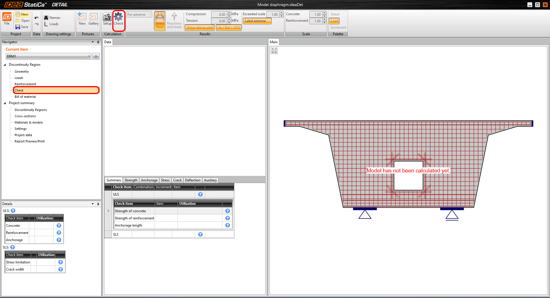
In the left bottom table, you can see the overview of all the code checks and the status of the checks (passed/failed).
In the table in the middle, all the detailed results can be found. In the first tab Summary, you can immediately see the governing ULS and SLS check together with maximum utilization for the particular entity.
In this example, the governing ULS check is Strength of reinforcement.
In the main window, there is a colored model of the diaphragm with the utilization of concrete and rebars. You can notice that the critical spots with maximum percentage utilizations are marked here.
The figure located above the detailed checks shows only the results for the current entity of the model.

By changing the top tabs, you can display all the code checks.
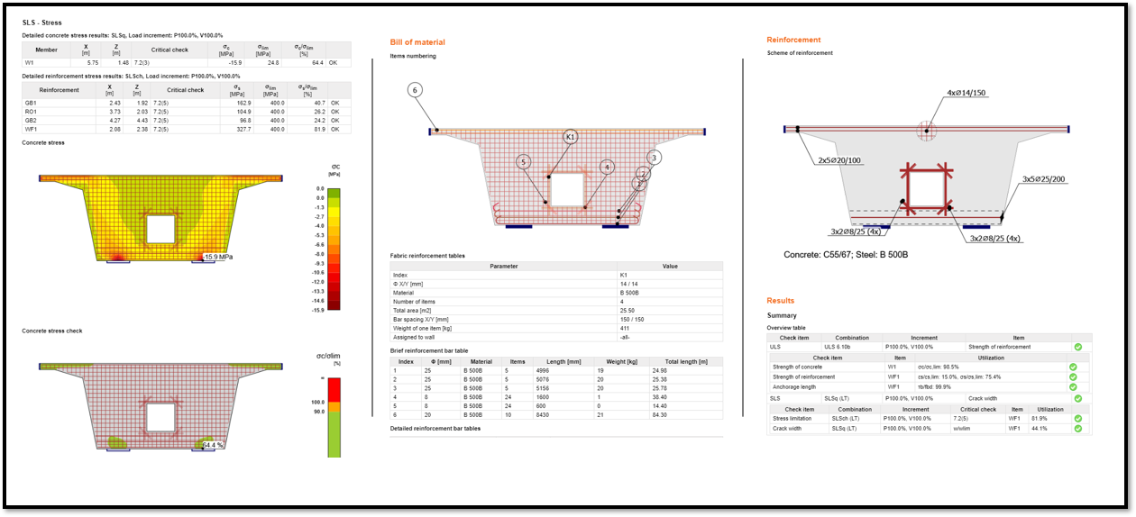
For example, on the Strength tab, you can examine the Principal stress σc in the concrete member and determine the highest stress concentration in the vicinity of the left bearing.

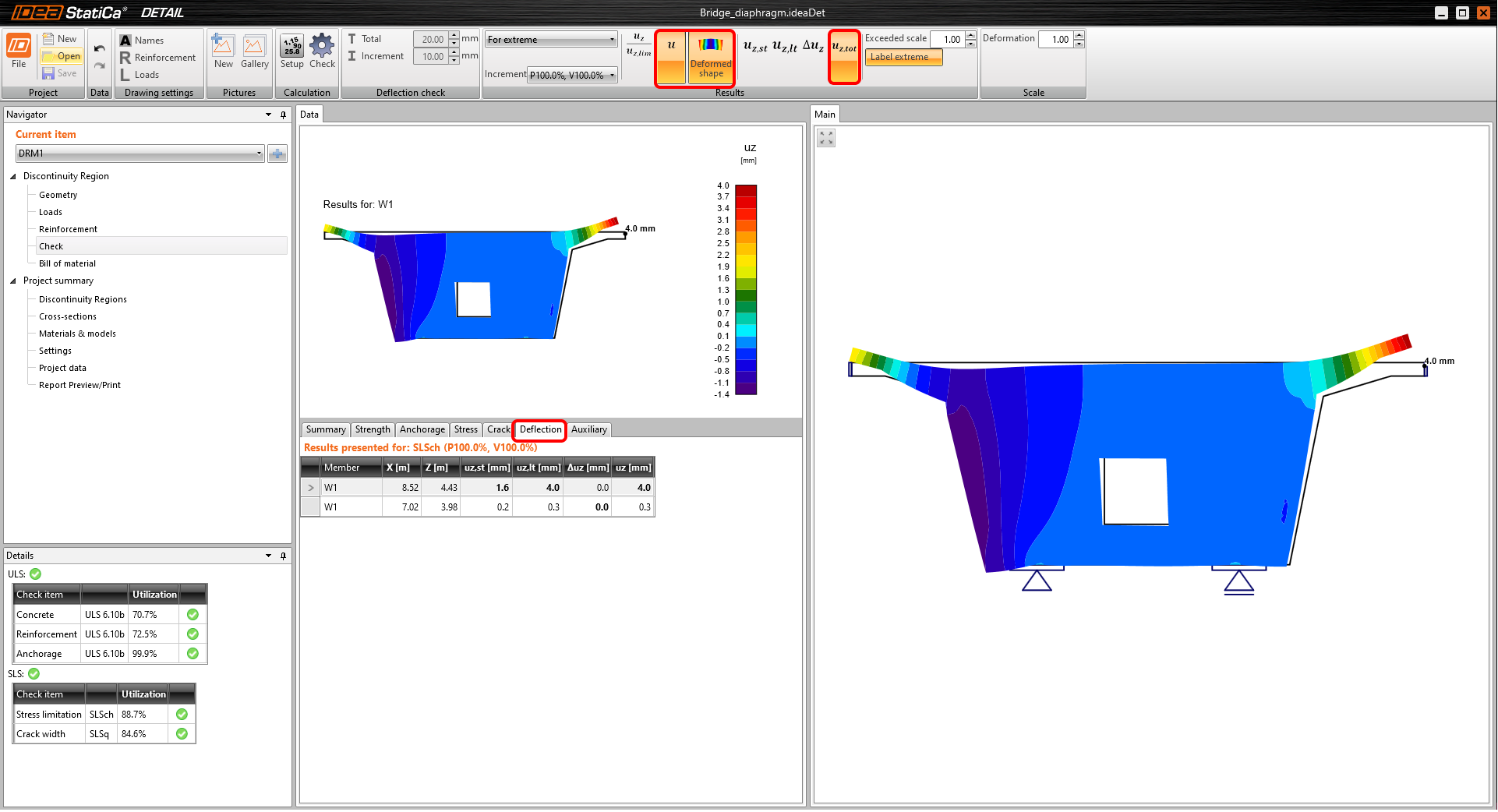
In terms of SLS checks, you can go through Stress limitation, Cracks or Deflection tabs. Check out the total deflection of the diaphragm. The deflections of the cantilevers upward are caused by the transverse prestressing force, which is eccentric to the section at the beginning of the haunch.
6 Report
At last, go to the Report Preview/Print. IDEA StatiCa offers a fully customizable report to print out or save in an editable format.

You have designed, optimized, and code-checked a bridge diaphragm according to Eurocode.