
1 New project
Start with launching IDEA StatiCa Member application (download the newest version). In the main window of IDEA StatiCa, open the Member application to define a new project.

For this example, it is necessary to set the number of decimal places for cross-section dimensions to "1". Go to the Units menu and make sure that these settings are made and click Apply.

Go to New menu and create a new project, type its name and select a folder where it will be saved. Then choose the design code and starting material properties.

Now you can define the type of topology. Finally, click on Create project and start modelling the structural details.

In this example, we use a Z-purlin as a single-span beam (5 m) with steel grade S 355. Other steel grades and other cross-sections can also be defined.

2 Analysed members
In this example, you have only one analysed member AM1, which was created at the same time as the project. The purlin should be aligned eccentrically; enter the value 340 mm in the offset ez field.

3 Related members
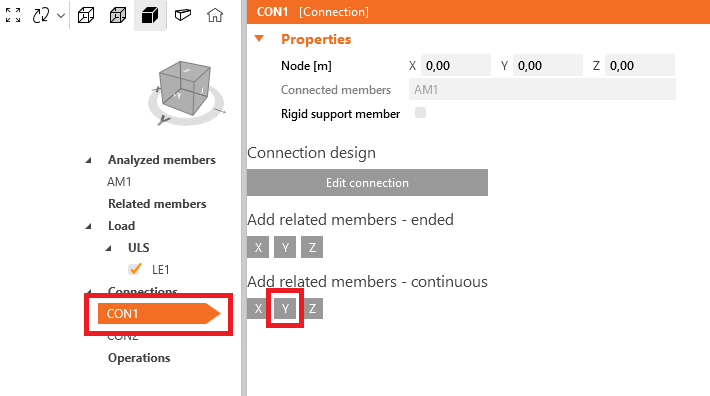
To add related members, which act as supports and load transferring parts for the structural detail, click on the node cube in the 3D scene or select a connection from the tree list. Here you can add either ended or continuous related members by clicking on the axis directions X, Y, Z according to the global coordinate system.
Boundary conditions at CON1
To add boundary conditions, click on connection CON1 and then on Add related members - continuous Y to add a continuous member to the existing joint.
Go to the newly created related member RM2 and change the cross-section to IPE400 (S235) and the supports at the begin to X Y Z Rx and at the end to Y Z Rx.

Add the next purlin in X direction by click on connection CON1 and then on Add related members - ended X.

Go to the newly created related member RM3 and change the cross-section to CFZed260x160 (S355), the offset ez to 340 mm, the direction X to -5 m, the support location to member axis and the support components to X Y Z Rx.

Boundary conditions at CON2
Click on connection CON2 and then on Add related members - continuous Y to Add a continuous member to the existing joint.

Go to the newly created related member RM4 and change the cross-section to IPE400 (S235) and the supports at the begin to X Y Z Rx and at the end to Y Z Rx.

Add the other purlin in X direction by clicking on connection CON2 and then on Add related members - ended X.

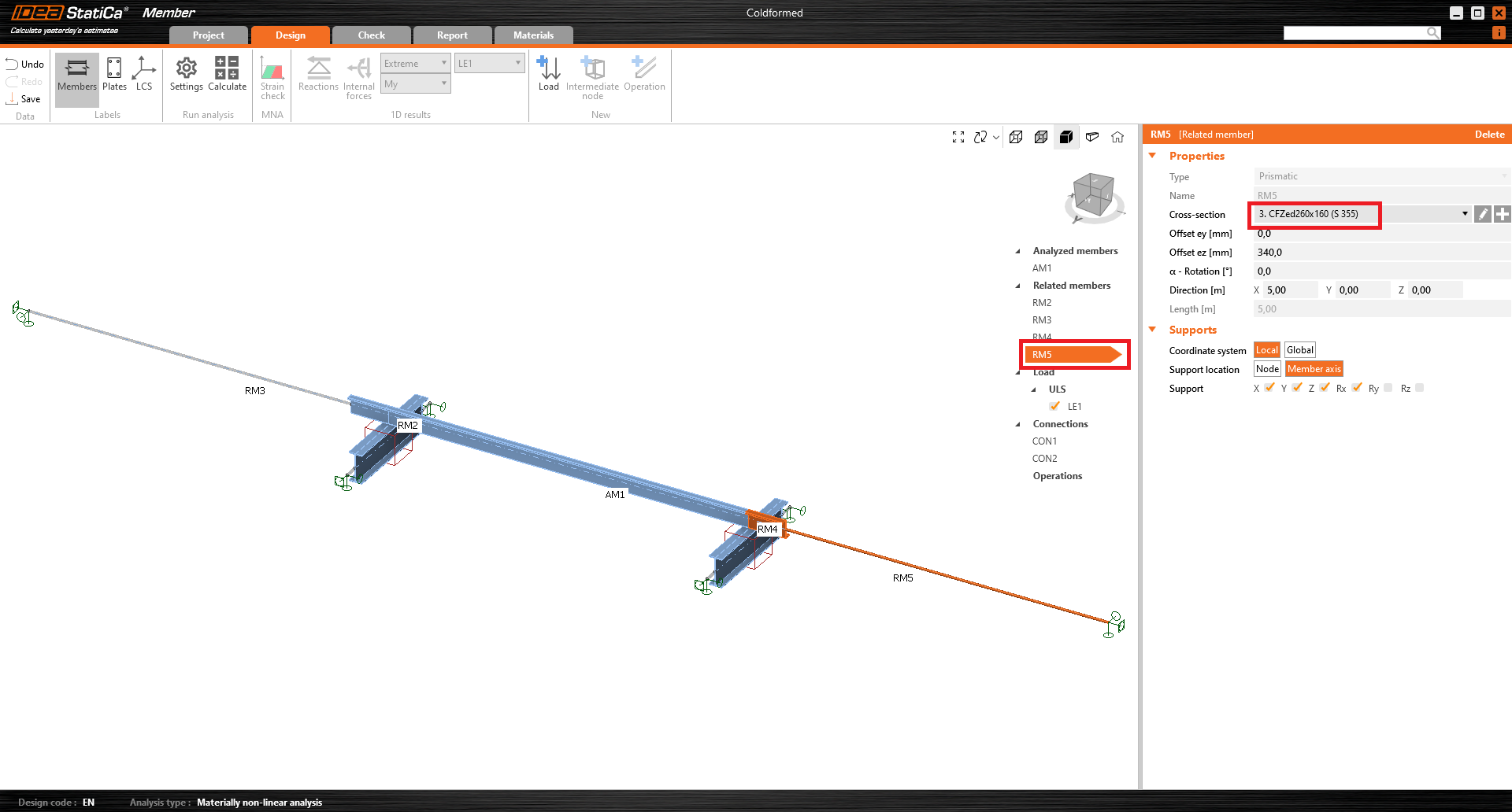
Go to the newly created related member RM5 and change the cross-section to a new CFZed260x160 (S355).

The purlin cross-section has been arranged mirror inverted. Therefore, we click on Add new (see see arrow above) to add mirrored cross-section by activating the checkbox Mirror by Z-axis.

Change the offset ez to 340 mm, the direction X to 5 m, the support location to Member axis and the support components to X Y Z Rx.

Now the geometry is correct and we can add the loads.
4 Loads
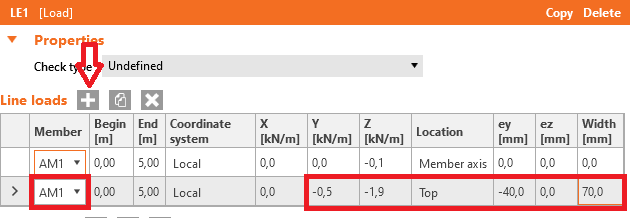
First, specify the dead load on the analysed member. We assume that 0.1 kN/m act in the Member axis of the purlin.

Now you can add local forces, acting on the top flange of the purlin. For each new load use the + button and enter the numbers according to the picture. Note that the line load is converted to an area load. The position and size of the area load must fit on the assigned cross-section part (IDEA StatiCa gives a warning if not). We assume that the system is inclined and therefore enter two load components.
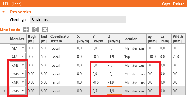
To simulate the correct boundary conditions, you have to place the loads on the related members. Use the copy button to speed up the input and apply the line loads to the related purlins.
5 Connections
Next, you can design the joints. Start with CON1 at the left site and click on Edit connection.

In a few seconds, IDEA StatiCa Connection application opens and you can design the joint by adding the manufacturing operations. The purlins AM1 and RM3 should be connected to the girder RM2 by a purlin cleat. Click on Operation in the New tab.

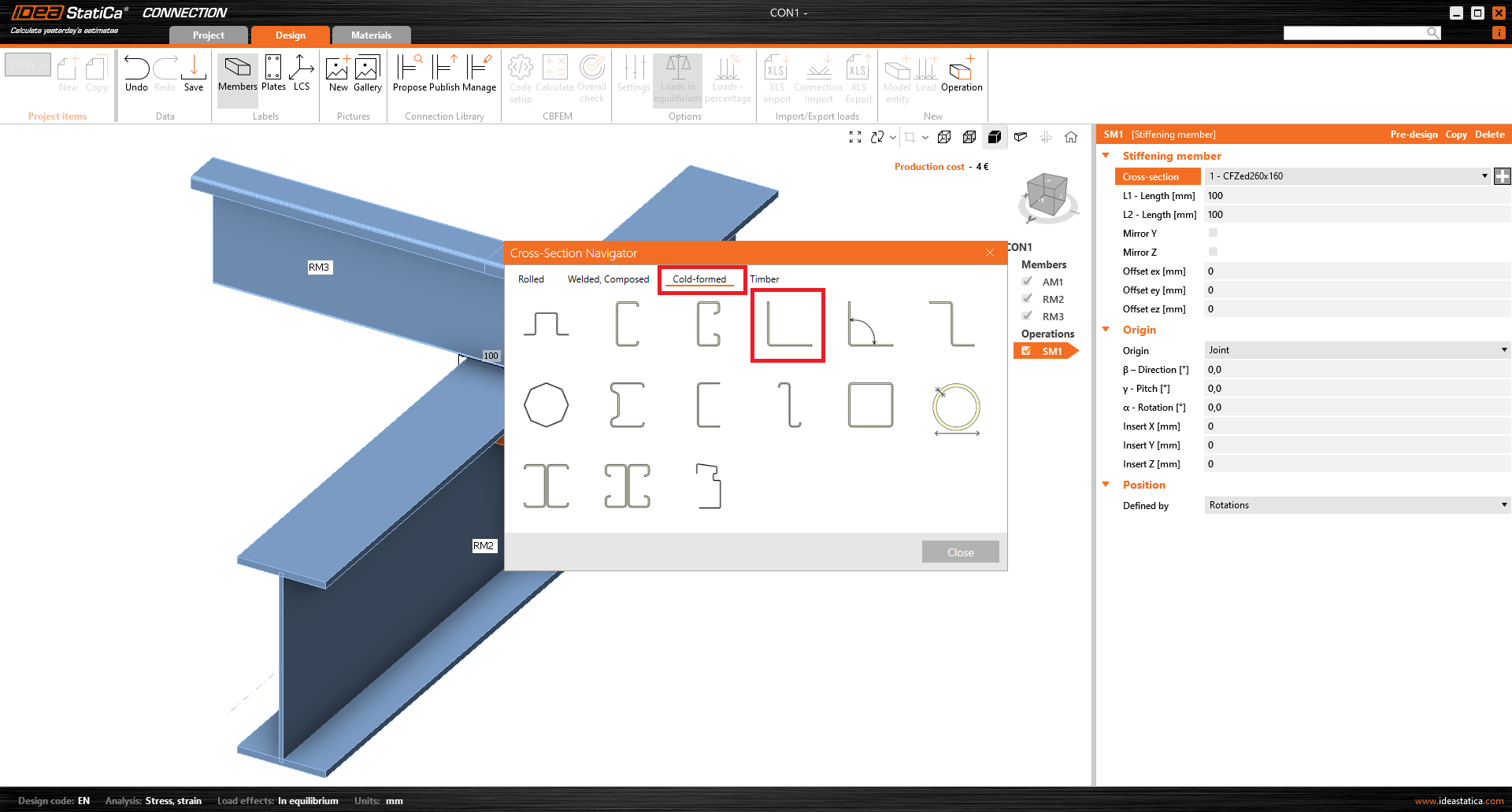
A purlin cleat consists of an L-shaped cross-section. In such cases, the best practice is to use a stiffening member operation and find a suitable cross-section that can be edited to a proper shape.

Then you have to add the new cross-section by clicking on + button and changing the cross-section according to the following pictures. This type of cross-section can be then easily transformed into a purlin cleat.

The purlin cleat is brought to the correct position by the following entries.

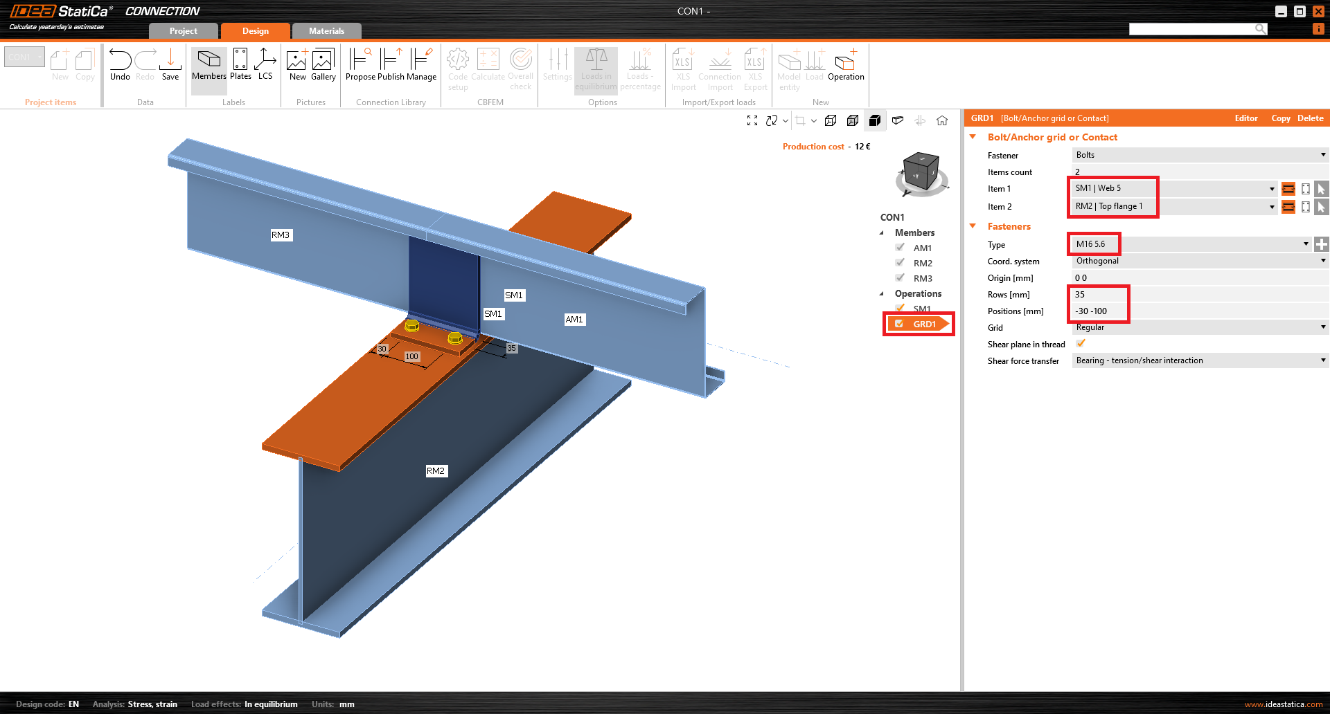
We first connect the purlin cleat SM1 to the top flange of RM2 by inserting the general bolt grid operation. As a bolt we choose M16 5.6.

The bolts are brought to the correct position by the following entries. Please note that to select items 1 and 2, the selection switch is set to Member.
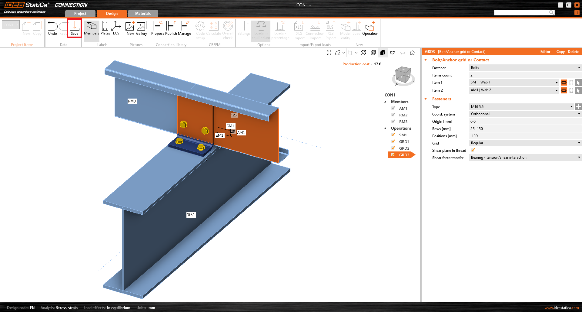
Now we connect the purlin cleat SM1 to the web of RM3 by copying the GRD1 operation (saves time) and do the following entries.

At the end we connect the web of AM1 to the purlin cleat by copying the GRD2 operation and do the following entries.

The joint is designed, now click Save and close the window.
We are back in the Member application. The second connection is designed in the same way. Click on Connection CON2 and then on Apply. Now the model is finished.

6 Check
IDEA StatiCa Member application offers the user the possibility to consider whole members with realistic end connections using FE shell elements. Thus, linear buckling analyses (LBA) and more advanced GMNIA are easier and more practical to perform.
A main task is the choice of appropriate imperfections, their amplitudes and possible combinations of local and global buckling cases. Since the system contains a thin-walled cross-section, a large number of relevant buckling modes can be expected.
In code setup we are increasing the number of buckling modes to 20.

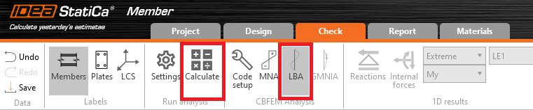
Now you can start the materially non-linear analysis. Select the tab check, MNA, and click calculate.

You can see the stresses along with the member by clicking on the button Stress in the upper ribbon.

After MNA calculation, a linear buckling analysis can be done by selecting LBA and clicking Calculate.
The first buckling mode is a local one. The best way to see the buckling shape is to click Usum.

The first global buckling mode is shape number 13. We will combine both buckling modes for GMNIA analysis.
For shape 1 we use the value d/200 = 260 mm / 200 = 1.3 mm.
For shape 13 we use the value L/200 = 5000 mm / 200 = 25 mm (curve c for flexural buckling around z–z axis). Imperfections are to be entered affine to the deformation from the MNA analysis. Therefore, we enter -25 mm.
More information about imperfections could be found in this article from IDEA StatiCa Support Center.

After setting the imperfections, a geometrically and materially non-linear analysis with imperfections can be done by selecting GMNIA and clicking Calculate.

You can browse through the results and see, that the dimension of the purlin is sufficient even with the geometrical imperfections.

7 Report
At last, go to the tab Report. IDEA StatiCa offers a fully customizable report to print out or save in an editable format.
